Device tree
Introduction
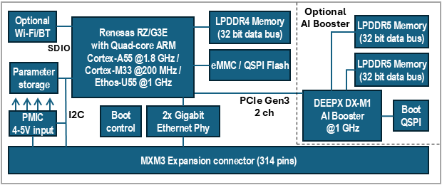
The device tree is a data structure used for describing hardware. Take a System-on-Module (SOM) such as the RZ/G3E SOM board as an example. It consists of several hardware devices (peripherals) such as RZ/G3E application processor, LPDDR4 memory, eMMC flash,Ethernet PHY, and Power Management IC (PMIC), see the figure below for a block diagram.
The RZ/G3E SOM board is then used in combination with a carrier board such as the SOM Carrier board used in a Developer’s Kit. This carrier board adds more peripherals and especially interfaces such as UART, USB, PCIe, SD card, audio codec, and more. To be even more specific the i.MX 8M application processor in itself also contains several peripherals such as I2C, SPI, PCIe, MIPI DSI, memory buses, and more.
To be able to use a hardware device within an operating system, (we will use Linux kernel as example), a device driver is needed. The driver needs to be initialized to work with the specific hardware / board configuration. This could for example be a device address (if attached to a bus), pin configuration, clock to assign to the device, and so on.
Before device trees, the Linux kernel often contained the board specific code, such as the address of the device. This meant that the kernel had to be re-compiled when something hardware specific had to be changed. Take a camera as an example. This device is attached to the I2C bus at a specific I2C address (0x36) and if the address had to be changed a new kernel had to be compiled. Another, but related problem, is if you offer different configurations of your product. In this case you had to provide different Linux kernels for each configuration in the case when the kernel contained board specific code.
The device tree solves these problems by moving board / device specific code out of the kernel and into the device tree file. This file can then be maintained and compiled separate from the kernel which will make the kernel more portable across different boards. In the example of using the Linux kernel the device tree will typically be loaded by the U-Boot bootloader.
It is important to note that a device tree won’t be needed for discoverable devices such as devices attached to a USB bus. The USB protocol has been designed to be able to detect if a device is attached and then probe that device for information that is given to the device driver.
Data structure format
The data structure can be seen as a tree structure with nodes and properties. Each node (except the root node) has one parent in the tree. A node contains a list of properties, which are key-value pairs, and can also contain child nodes. This kind of structure makes it quite easy for a human to read and understand how the hardware is organized.
The latest device tree specification can be found at https://www.devicetree.org/specifications/.
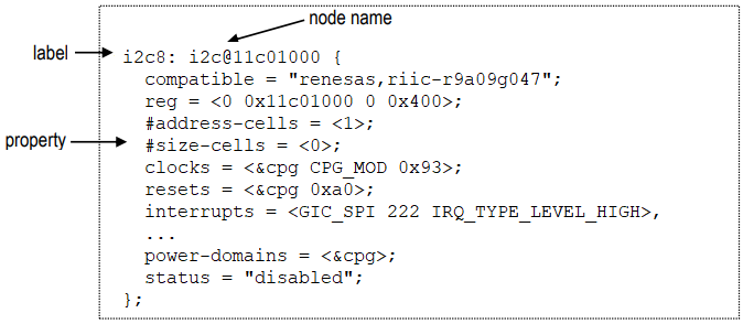
The figure below shows an example of a node that describes an I2C bus. In this example the node has been assigned a label (i2c8). This label can be used to reference the node from other parts of the device tree (instead of referencing the node name). The node name must be unique and should describe the general class of the device. In the example below the node name (i2c@11c01000) consists of a name (i2c) followed by a unit-address (@11c01000). The unit-address is omitted if there is no address associated with the device. In the example below you can see that the unit-address is also specified in the reg property.
One important property is the status property. Below you can see that it is set to disabled which means that the device won't be activated in the kernel.
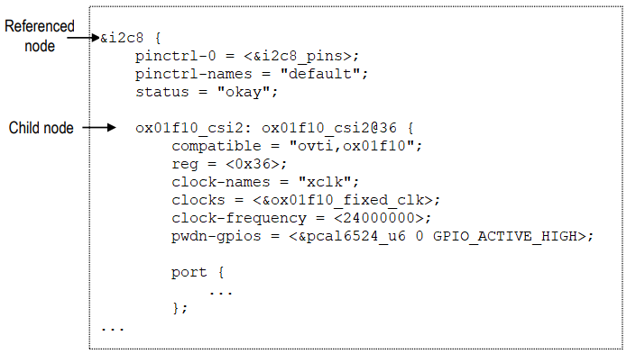
The figure below shows an example where the i2c8 node is referenced and properties added and changed. The status property is for example set to okay meaning that the I2C8 bus is activated. A child node (ox01f10_csi2) is added to the node since the actual camera device is attached to the I2C8 bus on the RZ/G3E Developer's Kit. For the camera device you can see that the I2C address is 0x36 (both set in the unit address field and the reg property).
Property values
As previously mentioned, properties consist of key-value pairs and the key (the property name) is a string of 1 to 31 characters. The value can however be of different types.
- Empty value. This indicates a true / false property and only contains the property name.
enable-active-high;
- String value.
status = "okay";
- String list. Strings are separated with comma (‘,’).
compatible = "renesas,r9a09g047-adc", "renesas,rzv2h-adc";
- Cell property array. The format is specific to the property. Below are two examples where the
regproperty contains one hexadecimal integer value, while thegpio_intrproperty contains one reference to another node and two integer values.reg = <0x36>;pwdn-gpios = <&pcal6524_u6 0 GPIO_ACTIVE_HIGH>;
- Binary data. The data is delimited with square brackets.
local-mac-address = [00 1A F1 01 04 15];
Aliases
There is a special node in the device tree called aliases. This node can be used to assign a short alias to a full node path. This alias can then be used within the Linux kernel or U-Boot when accessing a node instead of using the full path to the node. Aliases are not used within the device tree source (.dts) to reference a node. Instead, labels are used within the device tree source.
The example below, which is from rzg3e-ea-som.dtsi can look quite confusing since for example the alias serial1 reference sci2. The right-hand side is however in this case a label and means that the alias serial will have the value /serial@12801400, i.e., the full path to the serial node.
aliases {
mmc0 = &sdhi0;
mmc1 = &sdhi1;
mmc2 = &sdhi2;
ethernet0 = ð0;
ethernet1 = ð1;
serial0 = &scif;
serial1 = &sci2;
serial2 = &sci7;
The complete alias section for the RZ/G3E SOM can be seen by following the link below.
Source files and compiler
There are two types of source files used for device trees.
.dtsi– includable device tree file. This file is not considered a standalone device tree, but instead it is included in either another.dtsifile or in a .dts file that will complete the device tree. These types of files are typically used when describing the application processor, such asr9a09g047.dtsifor the RZ/G3E application processor..dts– This is a standalone device tree that can be compiled into a binary file (.dtb). Please note that a.dtsfile can include another.dtsfile. The file to include doesn't have to be a.dtsi. file.
A device tree source file is compiled into a binary device tree (.dtb) by using the device tree compiler (dtc). Most often you won't use this compiler directly, but instead build the .dtb files within the Linux kernel. In this case you will use the dtbs target.
make dtbs
Linux
Within the Linux kernel the device tree files are available under the arch directory. The exact location depends on which target you are using. This is what is used for the 64-bit RZ/G3E:
https://github.com/embeddedartists/linux-rz/tree/ea-6.1/arch/arm64/boot/dts/renesas
U-Boot
Within the U-Boot bootloader the device tree files are available under the arch/dts directory. Below you can see the exact location (for version 2024.07).
https://github.com/embeddedartists/uboot-rz/tree/ea_v2024.07/arch/arm/dts
Pin muxing
A pin on an RZ/G3E application processor may have more than one function, that is, it can be connected to more than one internal peripheral (but only one at a time). The selection of pin function is handled by an input-output multiplexer usually called IOMUX. Besides selecting which function to use the multiplexer is also used to configure other characteristics such as drive strength, hysteresis, open drain, pull-up/pull-down, and so on.
Pin muxing is handled in the device tree in a node called pinctrl. In this node you configure a pin within a child node that must contain the property pinmux with a value consisting of several cells.
If we take the I2C node from the Data structure format section as example you can see that it has a property called pinctrl-0 that has a reference to a node called i2c8_pins. The node i2c8_pins is a child node to pinctrl.
pinctrl-0 = <&i2c8_pins>;
Below is the i2c8_pins node with the pinmux property and a list of two pins being configured. Each row is a pre-processor macro that will be expanded to several cells. For the RZ/G3E this macro is defined in include/dt-bindings/pinctrl/rzv2h-pinctrl.h. In general, you don’t need to know the exact values set in the macro, but only how to interpret the values passed to the macro.
The RZV2H_PORT_PINMUX macro takes three arguments. The first two are the pin name and the last is for the pin function.
The RZV2H_PORT_PINMUX(3, 4, 4) means that pin P34 should have function 4.
The RZV2H_PORT_PINMUX(3, 5, 4) means that pin P35 should have function 4.
i2c8_pins: i2c8 {
  pinmux = <RZV2H_PORT_PINMUX(3, 4, 4)>, /* SCL */
           <RZV2H_PORT_PINMUX(3, 5, 4)>; /* SDA */
};
It is possible to control the output impedance by adding a property to the pinctrl node like this:
sd0-emmc-ctrl {
  pins = "SD0_CLK", "SD0_CMD";
  renesas,output-impedance = <3>;
};
Modify device tree from U-Boot
The U-Boot is responsible for loading the device tree and providing it to the Linux kernel. The U-Boot also has the fdt command that can be used to parse and modify the device tree before it is provided to Linux. By using the fdt command, you can make temporary changes to the device tree without having to modify and re-compile the .dts file.
Usage
From within the U-Boot console run the command below to get a description of which fdt commands that are available.
help fdt
Usage:
fdt addr [-c] <addr> [<length>]   - Set the [control] fdt location to <addr>
fdt boardsetup                    - Do board-specific set up
fdt systemsetup                   - Do system-specific set up
fdt move <fdt> <newaddr> <length> - Copy the fdt to <addr> and make it active
...
The commands that you will most often use are print, set, rm and possibly mknod.
Test different commands
This section describes how you can test some of the fdt commands.
Load the device tree
The device tree must be loaded before you can modify it. Do this by setting skip_booting and then running boot.
setenv skip_booting yes
boot
Setting bus to 8
switch to partitions #0, OK
mmc1 is current device
24918528 bytes read in 993 ms (23.9 MiB/s)
70581 bytes read in 5 ms (13.5 MiB/s)
!!!! Unset skip_booting variable to enable booting again !!!!
=>
Print the device tree
When the device tree has been loaded you can inspect it by using fdt print. You enter a path to the part of the tree you want to print. If you want to see the entire tree you print the root (‘/’). You can also use fdt list if you just want to print one level of nodes, for example, all children just beneath the root, but not any of the child nodes children.
Since the device tree is usually quite large it is better to only print the part you are interested in. You need to specify the complete path to the node or if an alias exist use that alias. If we take the I2C node described in the Data structure format section and list its content it looks like below. The I2C node is available directly under the root node.
fdt addr $fileaddr
fdt resize
fdt list /soc/i2c@11c01000
i2c@11c01000 {
        compatible = "renesas,riic-r9a09g047";
        reg = <0x00000000 0x11c01000 0x00000000 0x00000400>;
        interrupts = <0x00000000 0x000000de 0x00000004 0x00000000 0x0000020b 0x00000001 0x00000000 0x0000020a 0x00000001 0x00000000 0x000000e0 0x00000004 0x00000000 0x000000e1 0x00000004 0x00000000 0x000000df 0x00000004 0x00000000 0x000000e2 0x00000004 0x00000000 0x000000e3 0x00000004>;
        interrupt-names = "tei", "ri", "ti", "spi", "sti", "naki", "ali", "tmoi";
        clocks = <0x00000006 0x00000001 0x00000093>;
        resets = <0x00000006 0x000000a0>;
        power-domains = <0x00000006>;
        #address-cells = <0x00000001>;
        #size-cells = <0x00000000>;
        status = "okay";
        pinctrl-0 = <0x0000002b>;
        pinctrl-names = "default";
        codec@1a {
        };
        at24@55 {
        };
        gpio@21 {
        };
        gpio@23 {
        };
        gpio@22 {
        };
        clock-generator@68 {
        };
        eeprom@52 {
        };
        ox01f10_csi2@36 {
        };
};
You can get the same result by using the alias i2c8. See the Aliases section for information about aliases.
fdt list i2c8
Change the value of a property
Use fdt set to change the value of a property. In this example we will deactivate the eeprom which we could see as a child node to i2c@11c01000 in the example above.
fdt set /soc/i2c@11c01000/eeprom@52 status "disabled"
Boot Linux with the modified device tree
If you want to test the modifications you have done you cannot run just boot since this would mean that the device tree would be re-loaded. Instead you need to run some of the individual commands part of the boot process. In most cases this involves loading the image, setting the mmc arguments and then issuing the boot command. Which boot command to use can differ (booti or bootz) for different boards, but you can find it by inspecting the bootcmd variable. For the RZ/G3E SOM it looks like below.
run bootimage
Add to cmd_custom
If you want the modification of the device tree to be more permanent, that is, it should be done for consecutive boots without having to manually enter the fdt commands, you can add the changes to the cmd_custom variable.
setenv cmd_custom fdt addr \$fileaddr \; fdt resize \; fdt set /soc/i2c@11c01000/eeprom@52 status "disabled"
saveenv
Note the use of semicolon (';') to separate commands. Don't forget to escape ('') the semicolon otherwise it will be interpreted incorrectly by the U-Boot.
If you set a variable to something that causes the board to fail to boot then run env default -a followed by saveenv to restore the environment to its default state and it will possible to boot again.
Tools
The sections below have been flagged with TARGET and/or HOST to show where the command is typically used.
DTC (TARGET and HOST)
The Device Tree Compiler, dtc, is used under the hood when compiling the device tree source files using the make dtbs
command. It can however also be used standalone to compile or decompile single files.
The dtc command is not included in the ea-image-base yocto image, but it can be added by including IMAGE_INSTALL:append += "dtc"
in conf/local.conf.
To decompile a dtb file (either on target or on the host computer):
dtc -I dtb -O dts -o my_decompiled.dts rzg3e-ea-som-hdmi.dtb
The my_decompiled.dts file can then be modified and then compiled back into a dtb file with
dtc -I dts -O dtb -o rzg3e-ea-som-hdmi.dtb my_decompiled.dts
dtx_diff (HOST)
The dtx_diff is a script that, among other things, compares two dtb files without you having to decompile them to dts first.
The dtx_diff script is available in the scripts/dtc folder.
One example, comparing the compiled version of rzg3e-ea-som-hdmi.dts to rzg3e-ea-som-hdmi-ov5640.dts
./scripts/dtc/dtx_diff arch/arm64/boot/dts/renesas/rzg3e-ea-som-hdmi{,-ov5640}.dtb
--- arch/arm64/boot/dts/renesas/rzg3e-ea-som-hdmi.dtb
+++ arch/arm64/boot/dts/renesas/rzg3e-ea-som-hdmi-ov5640.dtb
@@ -6,6 +6,33 @@
        compatible = "renesas,r9a09g047e57-smarc\0renesas,r9a09g047e57\0renesas,r9a09g047";
        model = "Embedded Artists RZ/G3E SOM";

+       1p5v {
+               compatible = "regulator-fixed";
+               phandle = <0x33>;
+               regulator-always-on;
+               regulator-max-microvolt = <0x16e360>;
+               regulator-min-microvolt = <0x16e360>;
+               regulator-name = "camera_vddd";
+       };
+
+       1p8v {
+               compatible = "regulator-fixed";
+               phandle = <0x34>;
+               regulator-always-on;
+               regulator-max-microvolt = <0x1b7740>;
+               regulator-min-microvolt = <0x1b7740>;
+               regulator-name = "camera_vdddo";
+       };
+
+       2p8v {
+               compatible = "regulator-fixed";
+               phandle = <0x32>;
+               regulator-always-on;
+               regulator-max-microvolt = <0x2ab980>;
+               regulator-min-microvolt = <0x2ab980>;
+               regulator-name = "camera_vdda";
+       };
+
        aliases {
Only showing the first part of the diff.
/proc/device-tree (TARGET)
Sometime it is helpful to check the value of some dtb entry, for debugging, or checking that your dtb really got updated after you modfified, etc. An alternative to decompiling the dtb file is to check values using the entries in /proc/device-tree.
# ls /proc/device-tree/
#address-cells        dsi-to-hdmi-out       name                  regulator0
#size-cells           et0_rxc_rx_clk        opp-table-0           regulator1
aliases               et0_txc_tx_clk        opp-table-1           reserved-memory
audio-clka            et1_rxc_rx_clk        osc25250-clk          rtxin-clk
audio-clkb            et1_txc_tx_clk        psci                  soc
audio-clkc            gpio-keys             ptp_clock             sound
audio-extal-clk       keys                  qextal-clk            thermal-zones
cec-clock             memory@48000000       regulator-vcc-sdhi1   timer
chosen                mmngr                 regulator-vcc-sdhi2   vspm_if
compatible            mmngrbuf              regulator-vccq-sdhi1  x2-clock
cpus                  model                 regulator-vccq-sdhi2
# ls /proc/device-tree/aliases/
ethernet0  i2c0       i2c2       i2c4       i2c6       i2c8       mmc1       name       serial1
ethernet1  i2c1       i2c3       i2c5       i2c7       mmc0       mmc2       serial0    serial2
# cat /proc/device-tree/aliases/i2c8
/soc/i2c@11c01000
# ls /proc/device-tree/soc/i2c@11c01000/
#address-cells      compatible          interrupts          reg
#size-cells         eeprom@52           name                resets
at24@55             gpio@21             ox01f10_csi2@36     status
clock-generator@68  gpio@22             pinctrl-0
clocks              gpio@23             pinctrl-names
codec@1a            interrupt-names     power-domains
# ls /proc/device-tree/soc/i2c@11c01000/gpio@21/
#gpio-cells            hog_M2B_PERST          interrupt-controller   pinctrl-names
#interrupt-cells       hog_M2E_PERST          interrupt-parent       reg
compatible             hog_M2E_WL_REG_ON_3V3  interrupts
gpio-controller        hog_M2M_PERST          name
gpio-line-names        hog_SE050_EN_RST       pinctrl-0
dt_to_config (HOST)
The dt_to_config is a script to help find which Linux kernel configuration flags and drivers correspond to a node in the device tree. This is a part of the script's own documentation:
This program uses heuristics to guess which driver(s) support each compatible string and which config option(s) enables the driver(s). Do not believe that the reported information is fully correct. This program is intended to aid the process of determining the proper kernel configuration for a device tree, but this is not a fully automated process -- human involvement may still be required!
The driver match heuristic used is to search for source files containing the compatible string enclosed in quotes.
This program might not be able to find all drivers matching a compatible string.
The dt_to_config script is available in the scripts/dtc folder.
The script should be run from the root directory of the Linux kernel source tree.
Here we want information about the rzg3e-ea-som-hdmi.dts file:
# cd ~/gits/linux-rz
# ./scripts/dtc/dt_to_config arch/arm64/boot/dts/renesas/rzg3e-ea-som-hdmi.dts

...
-d-c--------- : /soc/i2c@11c01000/eeprom@52 : atmel,24c02 : drivers/misc/eeprom/at24.c : CONFIG_EEPROM_AT24 : none
-d-c--------- : /soc/i2c@11c01000/gpio@21 : nxp,pcal6524 : drivers/gpio/gpio-pca953x.c : CONFIG_GPIO_PCA953X : none
The output above shows only two lines but in reality several pages of information is produced. The two lines
that have been singled out above shows the I2C nodes (eeprom@52 and gpio@21), their respective
compatible strings "atmel,24c02" and "nxp,pcal6524", the driver files and the CONFIG_ flags.
If you have configured your kernel (e.g. by running make defconfig) and you pass that .config file
as an argument to dt_to_config, then you will get a bit more information - the end of the line shows the
value of the configuration flag instead of none:
# cd ~/gits/linux-rz
# ./scripts/dtc/dt_to_config -c .config arch/arm64/boot/dts/renesas/rzg3e-ea-som-hdmi.dts

...
-d-c-------y- : /soc/i2c@11c01000/eeprom@52 : atmel,24c02 : drivers/misc/eeprom/at24.c : CONFIG_EEPROM_AT24 : y
-d-c-------y- : /soc/i2c@11c01000/gpio@21 : nxp,pcal6524 : drivers/gpio/gpio-pca953x.c : CONFIG_GPIO_PCA953X : y
...
/sys/kernel/debug/pinctrl/pinctrl-handles (TARGET)
The debug file system /sys/kernel/debug has some information about the pinmux configuration in use.
The information is available in the /sys/kernel/debug/pinctrl/pinctrl-handles file.
# cat /sys/kernel/debug/pinctrl/pinctrl-handles
Requested pin control handlers their pinmux maps:
...
device: 12440000.can current state: default
  state: default
    type: MUX_GROUP controller pinctrl-rzg2l group: canfd.can1 (6) function: canfd.can1 (6)
    type: MUX_GROUP controller pinctrl-rzg2l group: canfd.can5 (7) function: canfd.can5 (7)
...
The command prints a lot of information, the selected lines above corresponds to this fragment of the rzg3e-ea-som.dtsi:
canfd_pins: canfd {
    can1_pins: can1 {
        pinmux = <RZV2H_PORT_PINMUX(D, 6, 3)>, /* RX */
                 <RZV2H_PORT_PINMUX(D, 7, 3)>; /* TX */
    };

    can5_pins: can5 {
        pinmux = <RZV2H_PORT_PINMUX(4, 4, 3)>, /* RX */
                 <RZV2H_PORT_PINMUX(4, 5, 3)>; /* TX */
    };
};
Frequently asked questions
Do I need to create my own device tree file?
If you are developing your own product by using one of Embedded Artists SOM boards you will most likely need to develop your own carrier board. Your carrier board will contain the specific peripherals and interfaces needed by your product. This mean that you have to use your own .dts file that defines the peripherals you are using.
How do I create my own device tree file?
The recommendation is that you start with one of the files (there can be more than one) that has been created for the Embedded Artists Developer's Kit you are using, for example, rzg3e-ea-som-hdmi.dts if you are using RZ/G3E SOM.
-
Copy our .dts file and give it a new name for your product.
-
Modify your file so it matches your hardware. This usually involves removing nodes that you don't need, but also adding new nodes for peripherals that are new and specific to your hardware.
-
Add the new .dts file to the Makefile so that it will be built. Below is a link to the Makefile used for rzg3e-ea-som-hdmi.dts.
-
The U-Boot environment has a variable named fdt_file that defines which .dtb file to load. You have to either update this variable dynamically using setenv or change the default setting in the U-Boot source code.
-
Change dynamically in U-Boot environment (make sure that you use a .dtb file and not a .dts file)
setenv fdt_file boot/rzg3e-ea-som-hdmi.dtb
saveenv -
Change default values statically in U-Boot source. The link below shows where and how it is configured for RZ/G3E SOM. It is done in a similar way for the other boards.
https://github.com/embeddedartists/uboot-rz/blob/ea_v2024.07/include/configs/rzg3e-ea-som.h#L58
-
-
If you want your new file to be included in a Yocto image you must update the machine file. The link below goes to the machine file for the RZ/G3E SOM board. It is similar for the other boards.
https://github.com/embeddedartists/meta-ea-rz-dev/blob/scarthgap/conf/machine/rzg3e-ea-som.conf#L50
How do I find the device driver?
Given a node in the device tree, how do I find the associated device driver in the Linux kernel? The short answer is that you need to look at the compatible property and find a driver that match one of the strings in the string list.
Let's take the camera node from the previous example. The compatible property looks like below.
compatible = "ovti,ox01f10";
In the Linux kernel source directory search for tha string. As you can see below the string can be found in drivers/media/i2c/ox01f10.c.
cd gits/linux-rz
grep -r "ovti,ox01f10" drivers/
drivers/media/i2c/ox01f10.c: {.compatible = "ovti,ox01f10",},
If you open this file you can see the device table below which lists "ovti,ox01f10" as a compatible device. Note that for some drivers this is a very long list and the compatible string only have to match one of them.
static struct of_device_id ox01f10_of_match[] = {
        {.compatible = "ovti,ox01f10",},
        {},
};
How do I find which properties I can use?
When you need to add a new node in the device tree for a new hardware device you also need to know which properties to use.
The first step is to try to find already existing device tree files using the same kind of device. Search for the device in the kernel sources. If you find existing examples you can use this as a starting point, but should also double-check the actual device driver since the examples could be out-dated.
Find the device driver as described in How do I find the device driver and open that file. Look for functions beginning with of_ such as of_property_read_u32 or of_get_named_gpio.
For drivers/media/i2c/ox01f10.c that was given as an example in the How do I find the device driver section you can find such functions in ox01f10_power_get, see below for an excerpt where the clock-frequency property is retrieved.
ret = of_property_read_u32(client->dev.of_node, "clock-frequency", &xclk_freq);
if (ret) {
    dev_err(&(client->dev), "could not get xclk frequency\n");
    return ret;
}
Can I modify the device tree without re-compiling?
See the Pin muxing section for a way to do this from within the U-Boot console.
Can I delete a node / property?
Yes, if you want to delete an already defined node or a property from a new .dts file you can do this by /delete-node/ or /delete-property/, see below for examples.
&sdhi2 {
	pinctrl-0 = <&sdhi2_pins>;
	pinctrl-1 = <&sdhi2_pins>;
	pinctrl-names = "default", "state_uhs";

	vmmc-supply = <&vmmc_sdhi2>;
	vqmmc-supply = <&vccq_sdhi2>;
	bus-width = <4>;
	sd-uhs-sdr50;
	sd-uhs-sdr104;
	status = "okay";

	/delete-node/ vqmmc-regulator;
};
&i2c8 {

	/delete-node/ ox01f10_csi2@36;
	...
};
&lvds0 {
	/delete-property/ renesas,companion;
	status = "okay";
	...
How do I see which device tree file is used?
The fdt_file U-Boot environment variable specifies which device tree file it will load before
booting into Linux. To see the value of the environment variable:
-
Hit any key after booting to stop in the U-Boot and then run this command:
=> printenv fdt_file
fdt_file=boot/rzg3e-ea-som-hdmi.dtb
How do select which device tree file to use?
The fdt_file U-Boot environment variable specifies which device tree file it will load before
booting into Linux. Check with How do I see which device tree file is used? or How can I see in runtime which device tree files are available?
which file is used and which file you can select. This example selects the rzg3e-ea-som-lcd.dtb.
Hit any key after booting to stop in the U-Boot and then run these commands:
=> setenv fdt_file boot/rzg3e-ea-som-lcd.dtb
=> saveenv
How can I see in runtime which device tree files are available?
The device tree files are stored in the /boot/ folder on the root file system.
This can of course be changed by the user.
-
U-Boot (if booting from QSPI)
If you are booting from QSPI the mmc device number is
1and the partition2.Hit any key after booting to stop in the U-Boot and then run this command:
=> ext4ls 1:2 /boot
<DIR>       4096 .
<DIR>       4096 ..
<SYM>         34 Image
      24918528 Image-6.1.107-cip28-yocto-standard
         71188 rzg3e-ea-som-hdmi-ov5640.dtb
         70581 rzg3e-ea-som-hdmi.dtb
         70595 rzg3e-ea-som-lcd.dtb
         70299 rzg3e-ea-som-lvds0.dtb
         70571 rzg3e-ea-som-lvds01.dtb
70084 rzg3e-ea-som-lvds1.dtb -
U-Boot (if booting from eMMC)
If you are booting from eMMC the mmc device number is
0and the partition2.Hit any key after booting to stop in the U-Boot and then run this command:
=> ext4ls mmc 0:2 /boot
<DIR>       4096 .
<DIR>       4096 ..
<SYM>         34 Image
      24918528 Image-6.1.107-cip28-yocto-standard
         70701 rzg3e-ea-som-hdmi.dtb
         70715 rzg3e-ea-som-lcd.dtb
         70415 rzg3e-ea-som-lvds0.dtb
         70571 rzg3e-ea-som-lvds01.dtb
70204 rzg3e-ea-som-lvds1.dtb -
Linux
Regardless if you are booting from QSPI+uSD card or from eMMC, the dtb file are found in
/boot/.Boot into Linux and use these commands:
root@rzg3e-ea-som:~# ls -1 /boot/*.dtb
/boot/rzg3e-ea-som-hdmi-ov5640.dtb
/boot/rzg3e-ea-som-hdmi.dtb
/boot/rzg3e-ea-som-lcd.dtb
/boot/rzg3e-ea-som-lvds0.dtb
/boot/rzg3e-ea-som-lvds01.dtb
/boot/rzg3e-ea-som-lvds1.dtb
Where do I find more documentation about device tree usage?
The links below contain a lot of useful information about device trees.