Deploy Images (eMMC)
This page will guide you through setting upp the RZ/G3E SOM to boot from eMMC instead of QSPI and to have the root file system on the eMMC. To use a uSD card for the root file system, see Deploy Images (uSD) instead.
You will need the following files, all found in the tmp/deploy/images/rzg3e-ea-som/ folder in your yocto build:
| File | Description |
|---|---|
bl2_bp_mmc-rzg3e-ea-som.srec(note the mmc in the middle) | BL2 (Boot Loader Stage 2), especially within ARM Trusted Firmware (TF-A), is a crucial intermediate step that initializes hardware (like DDR memory), performs security checks (authentication), and loads the next-stage bootloader (like U-Boot or the OS kernel) into RAM, acting as the bridge between the initial ROM code (BL1) and the main operating system. |
fip-rzg3e-ea-som.srec | FIP, or Firmware Image Package, is a standardized container format (used heavily by ARM Trusted Firmware-A (TF-A), U-Boot, and other modern boot systems}) for bundling multiple firmware components (like the ARM Trusted Firmware (ATF), UEFI, U-Boot, SCP firmware, DRM code, etc.) into a single binary file (often fip.bin) that the initial boot ROM or BL2 stage can load, authenticate, and execute. It provides a unified way to manage and deliver complex boot chains, enabling features like secure boot and firmware updates by wrapping essential binaries with necessary metadata and certificates. |
Flash_Writer_SCIF_RZG3E_CUSTOM_LPDDR4X.mot | A utility program that recieves data from TeraTerm, prepares the flash, writes the data to the flash and optionally other configuration flags. |
ea-image-base-rzg3e-ea-som.rootfs.tar.gz (note the tar.gz extension) | The root file system for Linux. This file will be placed on a removable media and then upacked into the eMMC. |
ea-image-base-rzg3e-ea-som.rootfs.wic.gz (note the wic.gz extension) | The root file system for Linux. This file will be flashed onto a uSD card and used as file system when booting into linux to then unpack the real root file system from the tar.gz file above. |
Update bootloaders
Note that this step is only needed if you have made changes to the bootloader files. If only the root file system has been modified then this step can be skipped.
Prepare hardware
Begin by reading the Getting Started Guide for the board you are using. It shows how to setup the board and also gives an overview of the hardware. The next step is to put the board into OTG boot mode.
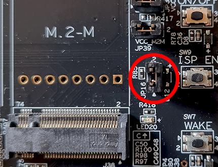
For the SOM Carrier board close jumper JP16 to put the board into OTG boot mode. You find this jumper to the left of the ISP_EN button.
Open TeraTerm
The bootloaders will be written to the RZ/G3E SOM over UART and using Tera Term. You can probably use another program but only TeraTerm has been tested. Connect to the virtual COM port using 115200 as baud rate, 8 data bits, 1 stop bit, and no parity.
Flash the bootloader
Power on the hardware by moving the ON/OFF switch to ON and then press and hold the POWER button for 3 seconds.
TeraTerm will show this:
SCI Download mode (Normal SCI boot)

-- Load Program to SRAM  ---------------
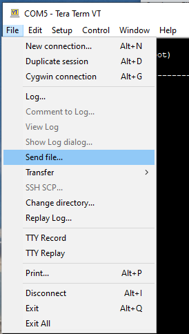
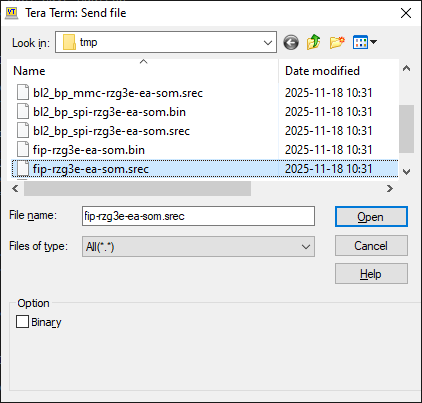
Click File->Send File... in the TeraTerm menu and select the Flash_Writer_SCIF_RZG3E_CUSTOM_LPDDR4X.mot file.

After successfully downloading the binary, Flash Writer starts automatically and shows a message like below on the terminal.
Flash writer for RZ/G3E Series V0.92 Aug.07,2025
 Product Code : RZ/G3E
>
The Flash Writer running, but the speed could be better so we'll increase it from 115200bps to 921600bps. To do this, run the SUPP command:
>SUP
Scif speed UP
Please change to 921.6Kbps baud rate setting of the terminal.
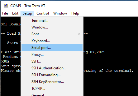
Now go to the Setup->Serial port... menu and then change to 921600 in the dialog and click OK to save the changes.

Make sure TeraTerm has focus and press the ENTER key on the keyboard. If you have successfully changed speed you should now see a prompt like this:
>
Now it is time to send the bootloader files, one at a time, to the Flash Writer.
| File name | Partition to save to eMMC | Address to save to eMMC | Address to load to RAM |
|---|---|---|---|
| bl2_bp_mmc-rzg3e-ea-som.srec | 1 | 1 | 8003600 |
| fip-rzg3e-ea-som.srec | 1 | 300 | 0 |
In TeraTerm, use the EM_W command and answer the questions. In the first prompt enter 1, in the second enter 1 and in the third 8003600:
>EM_W
EM_W Start --------------
---------------------------------------------------------
Please select,eMMC Partition Area.
 0:User Partition Area   : 30539776 KBytes
  eMMC Sector Cnt : H'0 - H'03A3FFFF
 1:Boot Partition 1      : 32640 KBytes
  eMMC Sector Cnt : H'0 - H'0000FEFF
 2:Boot Partition 2      : 32640 KBytes
  eMMC Sector Cnt : H'0 - H'0000FEFF
---------------------------------------------------------
  Select area(0-2)>1
-- Boot Partition 1 Program -----------------------------
Please Input Start Address in sector :1
Please Input Program Start Address : 8003600
Work RAM (H'40000000-H'4FFFFFFF) Clear....
please send ! ('.' & CR stop load)
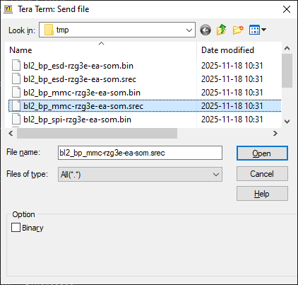
When the terminal tells you to send the file, use the File->Send file... menu and this time pick the bl2_bp_mmc-rzg3e-ea-som.srec file.
When the file has been transferred, the Flash Writer will start programming the flash. It will look like this.
SAVE -FLASH.......
EM_W Complete!
>
It will take a couple of seconds but wait for the > prompt to appear before continuing.
Now it is time for the second file to be programmed.
In TeraTerm, use the EM_W command and answer the questions. In the first prompt enter 1, in the second enter 300 and in the third 0:
>EM_W
EM_W Start --------------
---------------------------------------------------------
Please select,eMMC Partition Area.
 0:User Partition Area   : 30539776 KBytes
  eMMC Sector Cnt : H'0 - H'03A3FFFF
 1:Boot Partition 1      : 32640 KBytes
  eMMC Sector Cnt : H'0 - H'0000FEFF
 2:Boot Partition 2      : 32640 KBytes
  eMMC Sector Cnt : H'0 - H'0000FEFF
---------------------------------------------------------
  Select area(0-2)>1
-- Boot Partition 1 Program -----------------------------
Please Input Start Address in sector :300
Please Input Program Start Address : 0
Work RAM (H'40000000-H'4FFFFFFF) Clear....
please send ! ('.' & CR stop load)
When the terminal tells you to send the file, use the File->Send file... menu and this time pick the fip-rzg3e-ea-som.srec file.
When the file has been transferred, the Flash Writer will start programming the QSPI. It will look like this.
SAVE -FLASH.......
EM_W Complete!
>
It will take a couple of seconds but wait for the > prompt to appear before continuing.
The next thing is to modify the EXT_CSD register of the eMMC.
| Address | Value to write |
|---|---|
| 0xB1 | 0x02 |
| 0xB3 | 0x08 |
0xB3 (or decimal 179) is the BOOT_CONFIG register in the Extended CSD in the eMMC. Writing 0x08 to it enables boot
partition 1 for booting. It is actually bits 5:3 (i.e. the BOOT_PARTITION_ENABLE bits) that are written to.
- value 0x0, write 0x00, device not boot enable
- value 0x1, write 0x08, boot partition 1 enabled for boot
- value 0x2, write 0x10, boot partition 2 enabled for boot
- value 0x7, write 0x38, user area enabled for boot
0xB1 (or decimal 177) is the BOOT_BUS_WIDTH register. Writing 0x02 to it increases the
default bus width to 8 bit:
- 0x00 = 1 bit data bus
- 0x01 = 4 bit data bus
- 0x02 = 8 bit data bus
Information is from this JEDEC standard pdf
In TeraTerm, use the EM_SECSD command and answer the questions. In the first prompt enter b1 and in the second enter 2:
>EM_SECSD
  Please Input EXT_CSD Index(H'00 - H'1FF) :b1
  EXT_CSD[B1] = 0x00
  Please Input Value(H'00 - H'FF) :2
  EXT_CSD[B1] = 0x02
In TeraTerm, use the EM_SECSD command and answer the questions. In the first prompt enter b3 and in the second enter 8:
>EM_SECSD
  Please Input EXT_CSD Index(H'00 - H'1FF) :b3
  EXT_CSD[B3] = 0x01
  Please Input Value(H'00 - H'FF) :8
  EXT_CSD[B3] = 0x08
Now the bootloader is updated and it is time to write the file system to the eMMC. Remove the JP16 jumper that was inserted in the Prepare hardware step. Move the ON/OFF switch to OFF. Don't forget to set the serial port speed back to 115200 in TeraTerm before booting normally.
Write root file system to removable media
The root file system (ea-image-base-rzg3e-ea-som.rootfs.tar.gz) must be accessable from Linux running on the
RZ/G3E SOM. It can be on the same uSD card you use to boot from or on a USB memory.
Prepare a uSD card
Writing the file system requires booting into Linux from a uSD card. Prepare a uSD card as described in Flash root fs to an uSD card using the ea-image-base-rzg3e-ea-som.rootfs.wic.gz file.
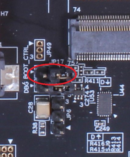
Boot Control
Make sure the BOOT_CTRL jumper (JP17) is shorted (to boot from eMMC). If it is open the board will boot from QSPI.
Update U-Boot variables to uSD boot
Power on the hardware by moving the ON/OFF switch to ON and then press and hold the POWER button for 3 seconds.
Press any key to stop in the U-Boot.
In TeraTerm, run the following 4 commands:
env default -a
setenv bootargs 'console=ttySC0,115200 rw rootwait earlycon root=/dev/mmcblk1p2'
setenv bootcmd 'mmc dev 1;ext4load mmc 1:2 0x48080000 /boot/Image;ext4load mmc 1:2 0x48000000 /boot/rzg3e-ea-som-hdmi.dtb;booti 0x48080000 - 0x48000000'
saveenv
The bootloader is now configured to load the Linux image and device tree files from the uSD - not the eMMC.
Boot into Linux on uSD card
Insert the uSD card that you prepared in Prepare a uSD card into the SOM Carrier Board.
In TeraTerm (still in the U-Boot), run this command to reboot the system.
reset
(An alternative is to press the SW6 Reset button).
When asked for a username at the login prompt, use root with no password.
Make partition tables on eMMC using fdisk
Run fdisk /dev/mmcblk0 to partition the eMMC. These are the answers to give when prompted:
| Prompt | Answer to give | Why? | | ------ | -------------- | | Command (m for help): | o | To create a new empty DOS partition table | | Command (m for help): | n | To add a new partition | | Partition type | p | To create a primary partition | | Partition number | 1 | | | First sector | (press the enter key) | Pressing enter to accept the default value, 16 | | Last sector | +500M | To create a 500Mb large partition | | Command (m for help): | n | To add a new partition | | Partition type | p | To create a primary partition | | Partition number | 2 | | | First sector | (press the enter key) | Pressing enter to accept the default value | | Last sector | (press the enter key) | Pressing enter to use the remaining space | | Command (m for help): | w | To write (i.e. save) the changes |
It should look like this:
root@rzg3e-ea-som:~# fdisk /dev/mmcblk0
Device contains neither a valid DOS partition table, nor Sun, SGI, OSF or GPT disklabel
Building a new DOS disklabel. Changes will remain in memory only,
until you decide to write them. After that the previous content
won't be recoverable.


The number of cylinders for this disk is set to 954368.
There is nothing wrong with that, but this is larger than 1024,
and could in certain setups cause problems with:
1) software that runs at boot time (e.g., old versions of LILO)
2) booting and partitioning software from other OSs
   (e.g., DOS FDISK, OS/2 FDISK)

Command (m for help): o
Building a new DOS disklabel. Changes will remain in memory only,
until you decide to write them. After that the previous content
won't be recoverable.


The number of cylinders for this disk is set to 954368.
There is nothing wrong with that, but this is larger than 1024,
and could in certain setups cause problems with:
1) software that runs at boot time (e.g., old versions of LILO)
2) booting and partitioning software from other OSs
   (e.g., DOS FDISK, OS/2 FDISK)

Command (m for help): n
Partition type
   p   primary partition (1-4)
   e   extended
p
Partition number (1-4): 1
First sector (16-61079551, default 16):
Using default value 16
Last sector or +size{,K,M,G,T} (16-61079551, default 61079551): +500M

Command (m for help): n
Partition type
   p   primary partition (1-4)
   e   extended
p
Partition number (1-4): 2
First sector (1024016-61079551, default 1024016):
Using default value 1024016
Last sector or +size{,K,M,G,T} (1024016-61079551, default 61079551):
Using default value 61079551

Command (m for help): w
The partition table has been altered.
Format eMMC as ext4
To format the new partitions:
mkfs.ext4 /dev/mmcblk0p1
mkfs.ext4 /dev/mmcblk0p2
Write rootfs to eMMC
Insert the removable media created in Write root file system to removable media.
These instructions will assume a USB memory is used. If something else is used then adjust the mount command accordingly.
root@rzg3e-ea-som:~# mkdir /mnt_usb
root@rzg3e-ea-som:~# mount /dev/sda1 /mnt_usb/
Unpack the root file system into the eMMC:
root@rzg3e-ea-som:~# mount /dev/sda1 /mnt_usb/
root@rzg3e-ea-som:~# mount /dev/mmcblk0p2 /mnt
root@rzg3e-ea-som:~# tar -xf /mnt_usb/ea-image-base-rzg3e-ea-som.rootfs.tar.gz -C /mnt/
root@rzg3e-ea-som:~# umount /mnt
Unmount the removable medium:
root@rzg3e-ea-som:~# umount /mnt_usb/
Now unplug the removable medium and reboot.
Update U-Boot variables to eMMC boot
Reboot and then stop in the U-Boot by pressing any key to stop the autoboot sequence.
root@rzg3e-ea-som:~# reboot
In TeraTerm, run the following 4 commands:
env default -a
setenv bootargs 'console=ttySC0,115200 rw rootwait earlycon root=/dev/mmcblk0p2'
setenv bootcmd 'mmc dev 0;ext4load mmc 0:2 0x48080000 /boot/Image;ext4load mmc 0:2 0x48000000 /boot/rzg3e-ea-som-hdmi.dtb;booti 0x48080000 - 0x48000000'
saveenv
Unplug the uSD card as we will now use the rootfs on the eMMC instead.
Run the following command to reset and boot from the eMMC for the first time.
reset
At the login prompt use root as user name and no password.