Deploy Images (uSD)
This page will guide you through setting upp the RZ/G3E SOM to have the root file system on a uSD card. To use the onboard eMMC for the root file system, see Deploy Images (eMMC) instead.
You will need the following files, all found in the tmp/deploy/images/rzg3e-ea-som/ folder in your yocto build:
| File | Description |
|---|---|
bl2_bp_spi-rzg3e-ea-som.srec(note the spi in the middle) | BL2 (Boot Loader Stage 2), especially within ARM Trusted Firmware (TF-A), is a crucial intermediate step that initializes hardware (like DDR memory), performs security checks (authentication), and loads the next-stage bootloader (like U-Boot or the OS kernel) into RAM, acting as the bridge between the initial ROM code (BL1) and the main operating system. |
fip-rzg3e-ea-som.srec | FIP, or Firmware Image Package, is a standardized container format (used heavily by ARM Trusted Firmware-A (TF-A), U-Boot, and other modern boot systems}) for bundling multiple firmware components (like the ARM Trusted Firmware (ATF), UEFI, U-Boot, SCP firmware, DRM code, etc.) into a single binary file (often fip.bin) that the initial boot ROM or BL2 stage can load, authenticate, and execute. It provides a unified way to manage and deliver complex boot chains, enabling features like secure boot and firmware updates by wrapping essential binaries with necessary metadata and certificates. |
Flash_Writer_SCIF_RZG3E_CUSTOM_LPDDR4X.mot | A utility program that recieves data from TeraTerm, prepares the flash, writes the data to the flash and optionally other configuration flags. |
ea-image-base-rzg3e-ea-som.rootfs.wic.gz (note the wic.gz extension) | The root file system for Linux. |
Update bootloaders
Note that this step is only needed if you have made changes to the bootloader files. If only the root file system has been modified then this step can be skipped.
Prepare hardware
Begin by reading the Getting Started Guide for the board you are using. It shows how to setup the board and also gives an overview of the hardware. The next step is to put the board into OTG boot mode.
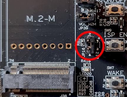
For the SOM Carrier board close jumper JP16 to put the board into OTG boot mode. You find this jumper to the left of the ISP_EN button.
Open TeraTerm
The bootloaders will be written to the RZ/G3E SOM over UART and using Tera Term. You can probably use another program but only TeraTerm has been tested. Connect to the virtual COM port using 115200 as baud rate, 8 data bits, 1 stop bit, and no parity.
Flash the bootloader
Power on the hardware by moving the ON/OFF switch to ON and then press and hold the POWER button for 3 seconds.
TeraTerm will show this:
SCI Download mode (Normal SCI boot)

-- Load Program to SRAM  ---------------
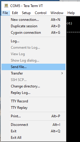
Click File->Send File... in the TeraTerm menu and select the Flash_Writer_SCIF_RZG3E_CUSTOM_LPDDR4X.mot file.

After successfully downloading the binary, Flash Writer starts automatically and shows a message like below on the terminal.
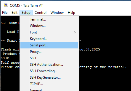
Flash writer for RZ/G3E Series V0.92 Aug.07,2025
 Product Code : RZ/G3E
>
The Flash Writer running, but the speed could be better so we'll increase it from 115200bps to 921600bps. To do this, run the SUPP command:
>SUP
Scif speed UP
Please change to 921.6Kbps baud rate setting of the terminal.
Now go to the Setup->Serial port... menu and then change to 921600 in the dialog and click OK to save the changes.

Make sure TeraTerm has focus and press the ENTER key on the keyboard. If you have successfully changed speed you should now see a prompt like this:
>
Now it is time to send the bootloader files, one at a time, to the Flash Writer.
| File name | Address to load to RAM | Address to save to ROM |
|---|---|---|
| bl2_bp_spi-rzg3e-ea-som.srec | 8003600 | 0 |
| fip-rzg3e-ea-som.srec | 0 | 60000 |
In TeraTerm, use the XLS2 command and answer the questions. In the first prompt enter 8003600 and in the second 0:
>XLS2
===== Qspi writing of RZ/G3E Board Command =============
Load Program to Spiflash
Writes to any of SPI address.
 Dialog : AT25QL128A
Program Top Address & Qspi Save Address
===== Please Input Program Top Address ============
  Please Input : H'8003600

===== Please Input Qspi Save Address ===
  Please Input : H'0
please send ! ('.' & CR stop load)
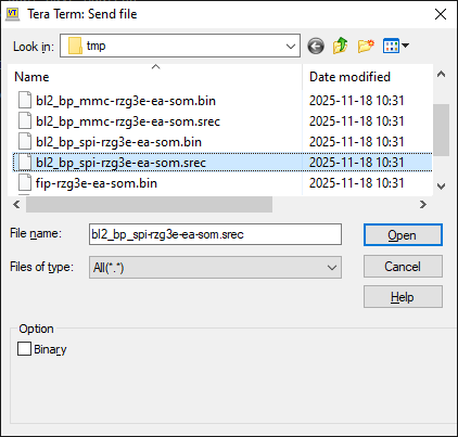
When the terminal tells you to send the file, use the File->Send file... menu and this time pick the bl2_bp_spi-rzg3e-ea-som.srec file.
When the file has been transferred, the Flash Writer will start programming the QSPI. It will look like this.
Erase SPI Flash memory...
Erase Completed
Write to SPI Flash memory.
======= Qspi  Save Information  =================
 SpiFlashMemory Stat Address : H'00000000
 SpiFlashMemory End Address  : H'00021170
===========================================================

>
It will take a couple of seconds but wait for the > prompt to appear before continuing.
If you get a prompt like below, please enter "y" to accept it. It is very unlikely that it will appear.
SPI Data Clear(H'FF) Check : H'00000000-0000FFFF,Clear OK?(y/n)
Now it is time for the second file to be programmed.
In TeraTerm, use the XLS2 command and answer the questions. In the first prompt enter 0 and in the second 60000:
>XLS2
===== Qspi writing of RZ/G3E Board Command =============
Load Program to Spiflash
Writes to any of SPI address.
 Dialog : AT25QL128A
Program Top Address & Qspi Save Address
===== Please Input Program Top Address ============
  Please Input : H'0

===== Please Input Qspi Save Address ===
  Please Input : H'60000
please send ! ('.' & CR stop load)
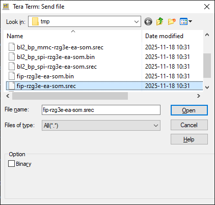
When the terminal tells you to send the file, use the File->Send file... menu and this time pick the fip-rzg3e-ea-som.srec file.
When the file has been transferred, the Flash Writer will start programming the QSPI. It will look like this.
Erase SPI Flash memory...
Erase Completed
Write to SPI Flash memory.
======= Qspi  Save Information  =================
 SpiFlashMemory Stat Address : H'00060000
 SpiFlashMemory End Address  : H'00148C4E
===========================================================

>
It will take a couple of seconds but wait for the > prompt to appear before continuing.
If you get a prompt like below, please enter "y" to accept it. It is very unlikely that it will appear.
SPI Data Clear(H'FF) Check : H'00000000-0000FFFF,Clear OK?(y/n)
Now the bootloader is updated and the board is ready to be used. Remove the JP16 jumper that was inserted in the Prepare hardware step. Move the ON/OFF switch to OFF. Don't forget to set the serial port speed back to 115200 in TeraTerm before booting normally.
Flash root fs to an uSD card
There are several ways of flashing an image onto a uSD card. Here we will use Balena Etcher but feel free to use something else.
- Download and install Balena Etcher from etcher.balena.io
- Start the program.
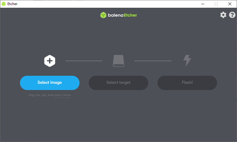
- Click Select Image and point to the
.wic.gzfile, for exampleea-image-base-rzg3e-ea-som.rootfs.wic.gz
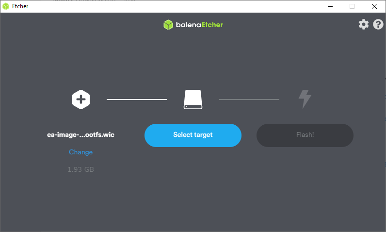
- Click Select Target and point to the uSD card to write to. Note that the entire card/partition/drive will be overwritten so choose carefully.
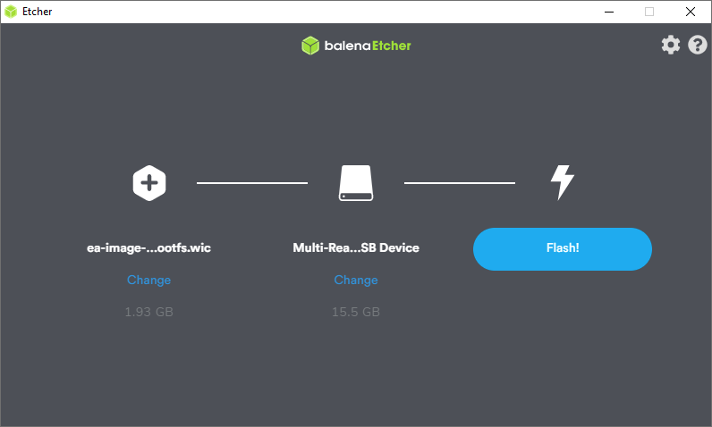
- Click Flash! to start
After the process completes, the uSD card is ready for use
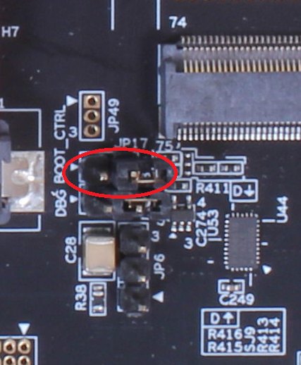
Boot Control
Make sure the BOOT_CTRL jumper (JP17) is open (to boot from QSPI). If it is shorted the board will boot from eMMC.