Analog Input - ADC
| Board | External signals | Precision | Maximum input voltage |
|---|---|---|---|
| RZ/G3E SOM | 8 signals divided into 1 channel with 8 inputs | 12 bit | 1.8V |
Note that input voltages above maximum input voltate will damage the CPU.
The analog pins are available on JP21 on the back side of the SOM Carrier Board:
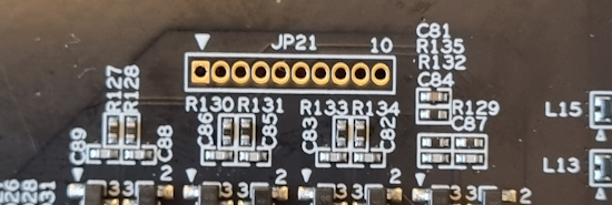
Pin 1 of JP21 is marked with a small triangle (left in the picture).
To safely test the ADC pins with the commands below, use a male-male jumper cable and connect the pin that you want to test with either pin 9 (for HIGH) or pin 10 (for LOW).
U-Boot
Not currently available.
Linux
Each ADC channel will be represented by a iio:device node in the file system.
ls /sys/bus/iio/devices/
iio:device0
ls /sys/bus/iio/devices/iio\:device0/
in_voltage0_get_value  in_voltage3_get_value  in_voltage6_get_value  power
in_voltage0_raw        in_voltage3_raw        in_voltage6_raw        subsystem
in_voltage1_get_value  in_voltage4_get_value  in_voltage7_get_value  uevent
in_voltage1_raw        in_voltage4_raw        in_voltage7_raw        waiting_for_supplier
in_voltage2_get_value  in_voltage5_get_value  name
in_voltage2_raw        in_voltage5_raw        of_node
In this case (RZ/G3E) the 8 signals are all in one channel (iio:device0) with 8 inputs (in_voltage0_raw, in_voltage1_raw, ... in_voltage7_raw).
To read the raw value (range is 0 - 4095 for 12 bit precision).
cat /sys/bus/iio/devices/iio\:device0/in_voltage2_raw
302
As the raw value is in range 0 - 4095 and the maximum input voltage is 1.8V you can scale the read value into mV like this:
actual_value = (raw_value * 1800) / 4095
| Raw | Actual Value |
|---|---|
| 0 | 0 mV |
| 302 | 132 mV |
| 4095 | 1800 mV |