Analog Output - PWM/GPT
The RZ/G3E CPU supports 16 GPT (General PWM Timer) which can be used for PWM output. However, only one is available on the SOM Carrier Board.
| SOM Carrier Board pin name | Available on | Pwm | GPT | DTS |
|---|---|---|---|---|
| BL_CONTRAST_PWM-GPIO | JP45 pin 1 | pwm0 | GPT1, GTIOC12A | gpt1_4 channel A |
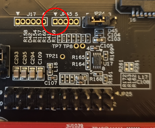
The PWM is available on pin BL_CONTRAST_PWM-GPIO which is used for backlight for LVDS0/1.
The rzg3e-ea-som-hdmi.dtb file has been configured to use that pin as a pwm0 instead. It can be accessed on JP45 pin 1:
The GPT peripheral has a lot of different possible use cases (described in r01us0484ej0110-rz_GPT_UME.pdf dowloadable from RZ/G3E Board Support Package). Here we will only show the basic PWM functionallity.
U-Boot
Not currently available.
Linux
To see which PWM channels have been enabled in the device tree.
ls /sys/class/pwm/
pwmchip0
Each PWM channel has its own pwmchipX folder with a couple of interesting files.
ls /sys/class/pwm/pwmchip0/
device     export  npwm      power
subsystem  uevent  unexport
To use a pwm channel it must first be exported.
echo 0 > /sys/class/pwm/pwmchip0/export
It will then appear as a pwm0 node. For echo 1 it would have been pwm1 and so on.
ls /sys/class/pwm/pwmchip0/pwm0
capture   duty_cycle   enable   period
polarity  power        uevent
To set the PWM frequency to 100 kHz (100kHz equals 10000 ns period time) and set the duty cycle to 70% (0.7 * period time equals 7000).
cd /sys/class/pwm/pwmchip0/pwm0
echo 10000 > period
echo 7000 > duty_cycle
echo 1 > enable
This signal can then be observed either with an oscilloscope or by measuring with a multimeter that will typically measure an average voltage. In this case the average should be ca 2.3V which is 70% of 3.3V.