Introduction
This page is a description of the M.2 interface and how it is used to create a very flexible system architecture when it comes to adding a Wi-Fi/BT interface in an embedded system. Specifically the solution provided by Embedded Artists is addressed, including an integration guide and information about regulatory certification.
What is M.2?
M.2 is a standard for internally mounted expansion cards. It is commonly found in so called ultrabooks, tablets, laptops and PC mother boards. It is also finding its way into more and more embedded systems designs.
The M.2 standard was formerly known as Next Generation Form Factor (NGFF) and has evolved from the mSATA and PCIe mini card standards.
Several different high-speed interface bus standards are supported, like PCIe, Serial ATA, USB and SDIO. M.2 modules can have several different functions implemented, including, but not limited to:
- Wi-Fi
- Bluetooth
- GPS - Satellite Navigation
- NFC - Near Field Communication
- Digital Radio
- WiGig
- Cellular Radio, including 2G/2.5G/3G/4G/5G
- WWAN - Wireless WAN
- SSD - Solid-State Drive
Form Factor
M.2 modules are rectangular and have an edge connector, with gold-plated fingers, on one side. Multiple module sizes are defined/supported by the standard. Width can be 12, 16, 22 or 30 mm and lengths can be 16, 26, 30, 38, 42, 60, 80 or 110 mm.
The M.2 module code contain both the width and length of the specific module, so for example, module code 2230 means that the module is 22 mm wide and 30 mm long. 2230 is a common form factor used for Wi-Fi/BT modules. The longer modules are typically used for large capacity SSD disks.
The M.2 connector has 75 positions, but due to keying (see below), only up to 67 positions can be used at the same time (less if multiple keying schemes are supported). The connector pitch is 0.5 mm.
The M.2 module code also contains information about top and bottom side maximum component height. To be safe always allow for 1.5 mm component height on both top and bottom side.
Keying
The M.2 connector has different keying notches (typically one but can be two) that demotes the supported hardware interfaces and the purpose of the connected M.2 module. There are different key identifications, represented by a single letter, A to M.
Embedded Artists' Wi-Fi/Bluetooth M.2 modules have key id: E, which defines pinning for PCIe (2x), SDIO, UART, PCM, USB2.0 and I2C interfaces.
Some key definitions overlap, for example A, B, E and M all supports at least one PCIe interface and B and M supports a SATA interface. An M.2 module can support two keying schemes at the same time and consequently have two key notches in the edge connector.
For more information about the M.2 standard, see: https://en.wikipedia.org/wiki/M.2
The official M.2 specification (PCI Express M.2 Specification) is available via membership from: www.pcisig.com
Non-standard M.2 Modules
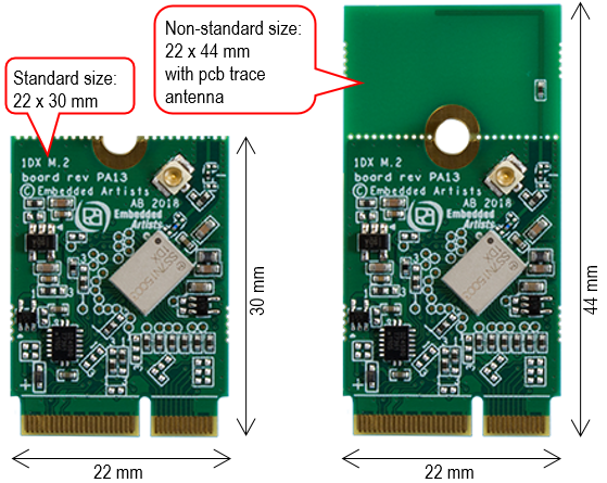
Embedded Artists has added a non-standard feature on some of the 2230 M.2 modules designed together with Murata, NXP and Infineon/Cypress. The pictures below illustrate how the standard module size has been extended by 14 mm in the length direction in order to include a PCB trace antenna.
The middle hole (or half hole) is the ground reference. It is important to ground this (half) hole with an M.2 screw with a larger head then normal M2 screws. Note that grounding is important even though the on-board PCB trace antenna is not used (or does not exist).
See the respective M.2 module datasheet for detailed information about clearance distances around the antenna.
M.2 modules with a pcb trace antenna has the antenna connected per default. It is possible to break-off the trace antenna to get a standard-sized M.2 module and then do a small rework to connect the antenna signal to the u.fl. antenna connector. See the respective M.2 module datasheet for detailed information about this rework.
Why Use M.2 Modules?
The obvious question is; Why use an M.2 module to add Wi-Fi/BT connectivity to a design?
Let's take a step back and look at the two main options available:
Wi-Fi/Bluetooth module A module integrates Wi-Fi/BT chipset, antenna PA, antenna switch, balun, crystal, passives and part of the power supply solution. A module is most often shielded, either with a metal can or a shielded resin is used to build the module. The pros and cons are listed below:
➕ One component in the BOM to order instead of many (50+)
➕ Can buy modules in small volume
➕ Requires less RF and general design competence to integrate
➕ Value-added module suppliers support the SW drivers for the module/chipset
➕ Modules can be reference certified, allowing easier/lower-cost regulatory certification for customers
➖ Higher cost than chipsetsWi-Fi/Bluetooth chipset A chipset can be integrated directly into the PCB of the design. The pros and cons are listed below:
➕ Lowest cost if the volume is high
➕ Most flexible solution
➖ Requires more RF and design competence. Requires some kind of shielding.
➖ Must make sure the chipset manufacturer will give SW support (which they will only do to very high-volume customers).
➖ You cannot buy the chipsets directly unless you have very high volumes (100K+ pcs/year).
➖ Very small pitch BGA packages that requires expensive PCB process. This is not a solution for large area PCBs because the whole PCB will be expensive.
➖ Test and certification cost is very high.
Given above, for volume below 100K pcs/year, the only real option is to use a Wi-Fi/BT module. Embedded Artists use Wi-Fi/BT modules from Murata to build M.2 modules. Murata is a value-added module supplier that provide excellent SW driver support.
To sum up and return to the question asked in the beginning of this section (Why use an M.2 module to add Wi-Fi/BT connectivity to a design?), there are multiple advantages of using M.2 modules in an embedded design, especially for lower volume design in the 1-20K pcs / year region.
- It is a modular and flexible approach to evaluate different Wi-Fi/BT solutions - with different trade-offs like performance, power consumption, range, cost, temperature range, supported standards, longevity, etc.
- It is a ready-to-go solution with minimal design work. No RF expertise is required - use the reference certified antenna or add external antenna
- Much more flexible solution than a direct solder down solution (that would require a redesign, and recertification if the module must be changed) -
- Supported by Embedded Artists' Developer's Kits for i.MX RT/6/7/8/9 development, including advanced debugging support on carrier boards. It also gives access to maintained software drivers (Linux and WICED) with responsive support from Murata.
Last, but not least, Embedded Artists' M.2 modules have been developed in close cooperation with Murata, NXP and Infineon/Cypress. This ensures excellent and professional support!
System Architecture
This section outlines the system architecture and relationships between different entities. The Device is the chipset implementing the wireless interface. The Device can implement this functionality fully, without external support, and is then called a Hostless system. The alternative is called a Hosted system, where a processor (application processor or microcontroller) downloads firmware to the Device. A driver in the Host processor communicates with the firmware in the Device and jointly implements the wireless interface. The M.2 modules are all Hosted, i.e., requires a host processor to implement the wireless interface.
The picture below illustrates a Hosted design in more detail.

There is one communication/interface channel between the host and device for the Wi-Fi data. This is either an SDIO, PCIe or USB interface. SDIO and PCIe are the most common.
There is also one communication/interface channel between the host and device for the Bluetooth data. This is typically a UART interface. There are some M.2 modules where Bluetooth and Wi-Fi share the same data channel interface. This can be over the SDIO, PCIe or USB interface. Note that sharing interface for the Bluetooth and Wi-Fi data channel is not the default solution. It will typically require a special driver from Murata or NXP.
The host has several control signals to the device. These control the overall power state and can also wake up the device if it is a sleep mode (to save power).
The device also has wakeup signals to the host, one for the Wi-Fi channel and one for the Bluetooth channel. These signals can wake up the host on specific wireless communication events, for example when receiving data.