Zephyr OS
Introduction
The Zephyr Project is an open source collaborative effort aiming to build a best-in-class small and scalable real-time operating system (RTOS). It has been highly accepted by the industry and already supports many architectures, several hundreds of boards as well as sensors, peripherals and other OS services.
It is developer friendly with extensive documentation, support for several toolchains on several host operating systems (Linux, macOS, and Windows). It is configurable via Kconfig and the hardware is described and abstracted via Device Tree files.
Supported Embedded Artists boards
The following boards currently have a Zephyr board support package. The board name given in the table below is the name to use with the -b option when building a sample application.
| Board | Board name in Zephyr |
|---|---|
| iMX RT1176 Developer's Kit | ea_rt1176_kit_cm7 for the Cortex-M7 core and ea_rt1176_kit_cm4 for the Cortex-M4 core |
Getting started
At the time of writing these instructions support for Embedded Artists boards have not yet been integrated into the official Zephyr repository. Instead, see the section about how to Use Embedded Artists repository
The official Zephyr Getting Started Guide is excellent. Please follow the guide to install Zephyr on your host OS. Embedded Artists has verified the instructions on an Ubuntu 22.04 host with successful result.
Use Embedded Artists repository
When getting to the Get Zephyr part of the Getting Started Guide you need to change the west init command to retrieve source code from the Embedded Artists repository.
These are the original instructions:
west init ~/zephyrproject
cd ~/zephyrproject
west update
Change to this instead.
west init -m https://github.com/embeddedartists/zephyr --mr add_board_ea_rt1176 ~/zephyrproject
cd ~/zephyrproject
west update
For more information about the west init command go to the official documentation.
Debug probe
A debug probe is used for both flashing and debugging a board. Several debug probes are supported by Zephyr, but only MCU-Link and MCU-Link Pro have currently been tested with the Embedded Artists boards.
Within Zephyr, and more specifically the west tools, flash and debug commands have been put in Python wrappers called runners.
MCU-Link with CMSIS-DAP
By default, the MCU-Link comes with CMSIS-DAP firmware. CMSIS-DAP based probes can be used with the linkserver runner. To be able to use this runner NXP's LinkServer must be installed. This can either be achieved by the MCUXpresso Installer or the LinkServer installer
Installing LinkServer on Ubuntu
Here is an example of how LinkServer was installed on a Ubuntu 22.04 host.
wget https://www.nxp.com/downloads/en/device-drivers/LINKSERVER-LIN_1.3.15.deb.bin
chmod a+x LINKSERVER-LIN_1.3.15.deb.bin
sudo ./LINKSERVER-LIN_1.3.15.deb.bin
export PATH=$PATH:/usr/local/LinkServer
It is possible to flash a board using the linkserver runner.
west flash --runner linkserver
It is also possible to debug an application from command line using gdb commands.
west debug --runner linkserver
MCU-Link with J-Link
The default and recommended runner for Embedded Artists boards is the jlink runner. It is possible to program an MCU-Link or MCU-Link Pro with J-Link firmware.
- The first step is to download and run the MCU-Link installer.
- Download the latest J-Link firmware and put in the
<mcu-link-installer-dir>/probe_firmwarefolder. - Install the J3 jumper on the MCU-Link or the 'FW update' jumper on MCU-Link Pro.
- Run
<mcu-link-installer-dir>/scripts/program_JLINK.cmd. - Uninstall the J3 jumper on the MCU-Link or the 'FW update' jumper on MCU-Link Pro.
The Segger J-Link Software and Documentation Pack must be installed before the J-Link runner can be used. At the time of writing these instructions V7.94b of the software was used. The software was installed on Ubuntu 22.04.
- Download the 64-bit DEB installer.
- Install with dpkg.
sudo dpkg -i JLink_Linux_V794b_x86_64.deb
Since J-Link is the default runner, it is possible to flash a board without using the --runner option.
west flash
It is also possible to debug an application from command line using gdb commands.
west debug
Visual Studio Code
Visual Studio Code (VS Code), an Integrated Development Environment (IDE), has gained popularity for its support of various programming languages and ecosystems. It can be used for Zephyr projects, but some configuration is required to fully optimize its functionality.
The instructions in this section are based on Jonathan Beri's talk at the 2023 Embedded Open Source Summit. Besides the blog and the video of the talk there is also a GitHub repository with example files.
We will use the Blinky application as an example when configuring a project for Visual Studio Code.
.code-workspace
Jonathan Beri's repository has an example of a workspace file to use. This section describes how to download, modify, and use it with the Blinky sample application.
-
Change directory to
samples/basic/blinky.cd ~/zephyrproject/zephyr/samples/basic/blinky/ -
Download the example file from Jonathan Beri's repository
wget https://raw.githubusercontent.com/beriberikix/zephyr-vscode-example/main/zephyr-linux.code-workspace -
If you installed the Zephyr SDK in your home directory (
$HOME) and the zephyr project in$HOME/zephyrprojectmost of the settings in.code-workspacewill be correct. -
In the downloaded
.code-workspacefile the Zephyr SDK version is 0.16.1, but we installed the latest version which was 0.16.4. Search and replace allzephyr-sdk-0.16.1to the version you have installed, in our casezephyr-sdk-0.16.4. -
In the downloaded
.code-workspacefile the board setting isnrf52840dk_nrf52840. Search and replace withea_rt1176_kit_cm7. -
The launch and attach configurations are using
nRF52840_xxAAas device. Change this toMIMXRT1176xxxA_M7. -
Now start VS code and then go to the menu 'File' > 'Open Workspace from file..' and then navigate to
zephyr-linux.code-workspace.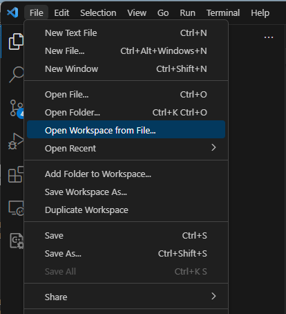
-
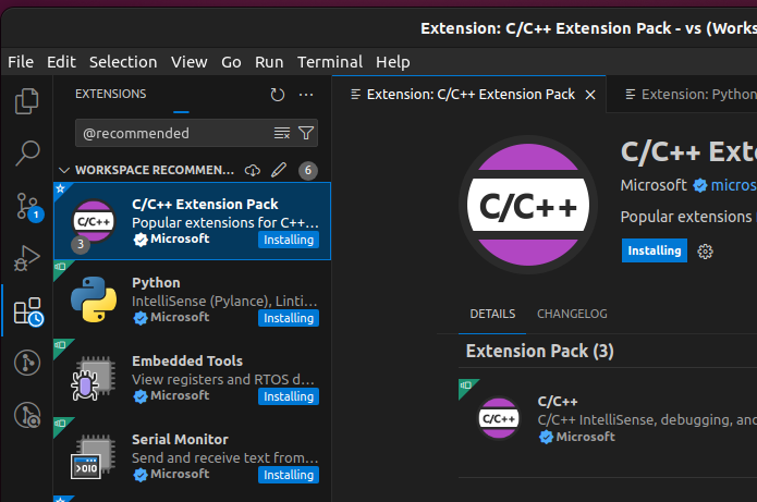
The first time you open the workspace file you will be asked to install recommended extensions. Please do this.
noteIf it seems as though installation of the extensions is stuck, restarting VS Code usually solves the problem. The image below shows four extensions with 'Installing' state never changing.
-
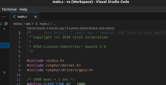
Open the
src/main.cfile. The first time you do this you will see "include errors" similar to the image below. The reason is that the compile commands file not being available. It won't be available until the project has been built at least once.
The command file is specified in the workspace file as below.
"C_Cpp.default.compileCommands": "${workspaceFolder}/build/compile_commands.json", -
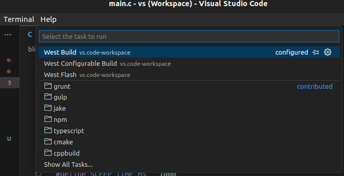
Build the project by going to the menu 'Terminal' > 'Run Task' and then 'West Build'
- The project has now been configured, built once, and you will no longer see the include errors.
Debug the application
As long as you are using a J-Link compatible debug probe, such as MCU-Link with J-Link firmware you can start to debug your application. The VS code workspace file (.code-workspace) has launch and attach configurations setup to be used with J-Link.
-
Click on the Run and Debug icon.
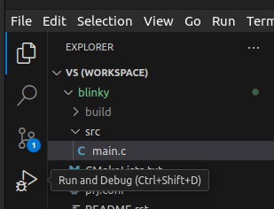
-
Click on the Launch icon.

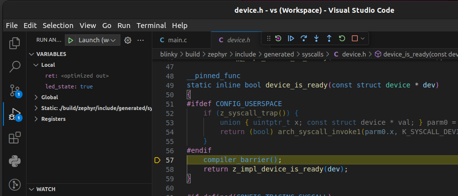
-
The application will now be flashed and started. You should see something similar to below when the debug session has halted. Just as with any debugger you can single step, set breakpoints and inspect variables and registers.
MCUXpresso extension
NXP has developed the extension MCUXpresso for Visual Studio Code. This extension can be used to create, build, and debug application using NXP's MCUXpresso SDK, but also Zephyr projects.
Read the chapter Working with Zephyr for more information.
Embedded Artists has not verified the use NXP's extension when working with Zephyr.
Features and sample applications
iMX RT1176 Developer's Kit
UART
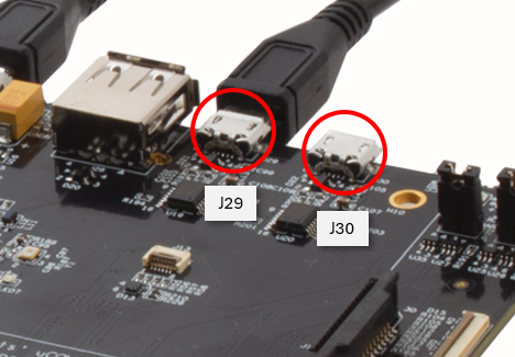
For the Cortex-M7 core, UART1 is used as console. Connect a USB cable between the J29 USB micro-B connector on the uCOM Carrier Board and your host computer.
For the Cortex-M4 core, UART6 is used as console. Connect a USB cable between the J30 USB micro-B connector on the uCOM Carrier Board and your host computer.
You can use samples/hello_world to test the UART.
Cortex-M7 core:
west build -b ea_rt1176_kit_cm7 samples/hello_world
Cortex-M4 core:
west build -b ea_rt1176_kit_cm4 samples/hello_world
GPIO/LED
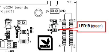
On the uCOM Carrier board, LED19 is GPIO mapped, more specifically it is connected to GPIO9.15. The LED is located on the right side of the board just above the uSD connector.
You can use samples/basic/blinky to blink with LED19. The application requires a devicetree alias called led0 to be associated with the LED.
west build -b ea_rt1176_kit_cm7 samples/basic/blinky
GPIO Expander - PCA6416
The uCOM Carrier Board has a PCA6416 GPIO Expander. This expander is connected to several LEDs as well as a User button.
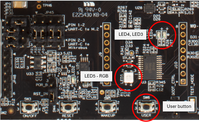
You can use samples/basic/button to test the User button. The application requires a devicetree alias called sw0 to be associated with the button.
west build -b ea_rt1176_kit_cm7 samples/basic/button
You can use samples/basic/blinky to blink with any of the other LEDs. Change the led0 alias in the application to any of the other aliases.
Ethernet
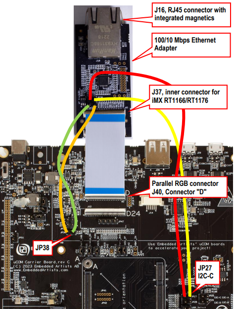
The iMX RT1176 uCOM board comes with an onboard Ethernet PHY which is using the ENET1G interface in RGMII mode. Unfortunately the ENET1G/RGMII mode is currently not supported in Zephyr. The iMX RT1176 Developer's Kit however comes with a 10/100 Mbit Ethernet adapter that can be used instead.
The uCOM Carrier Board datasheet, section 3.6, describes how to connect and use the Ethernet adapter.
You can use samples/net/dhcpv4_client to test the Ethernet interface.
west build -b ea_rt1176_kit_cm7 samples/net/dhcpv4_client
When the application boots it will try to get IP address settings from a DHCP server. Below is an example of how it can look like in the console.
*** Booting Zephyr OS build zephyr-v3.5.0-3203-gb4768d5d4241 ***
[00:00:00.510,000] <inf> net_dhcpv4_client_sample: Run dhcpv4 client
[00:00:00.510,000] <inf> net_dhcpv4_client_sample: Start on ethernet@40424000: index=1
[00:00:02.511,000] <inf> eth_mcux: ETH_0 enabled 100M full-duplex mode.
[00:00:05.767,000] <inf> net_dhcpv4: Received: 192.168.1.99
[00:00:05.767,000] <inf> net_dhcpv4_client_sample:    Address[1]: 192.168.1.99
[00:00:05.767,000] <inf> net_dhcpv4_client_sample:     Subnet[1]: 255.255.255.0
[00:00:05.767,000] <inf> net_dhcpv4_client_sample:     Router[1]: 192.168.1.1
[00:00:05.767,000] <inf> net_dhcpv4_client_sample: Lease time[1]: 86400 seconds
USB Device
Zephyr has USB device support. On the uCOM carrier board this can be tested by using the J26 micro-B USB connector.
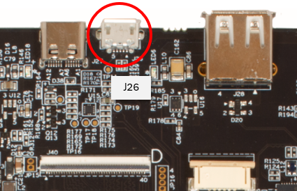
There are several USB device examples available. One that is easy to test is the samples/subsys/usb/console that will be detected as a CDC_ACM serial device. Attach a USB cable between J26 and your computer. Then connect a console to the serial port, and you will see "Hello World" as output.
west build -b ea_rt1176_kit_cm7 samples/subsys/usb/console
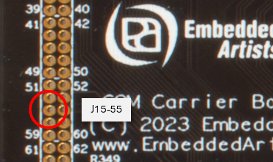
ADC
The i.MX RT1176 supports several Analog-to-Digital Converter (ADC) channels. One has been configured in the default pinxmux dtsi file. This specific signal is available on the uCOM Carrier Board on J15 expansion connector. More specifically on J15-55.
The ADC is not completely configured in the default device tree files. Instead, there is board specific overlay files in the sample application directory. The iMX RT1176 Developer's Kit is in this regard compatible with NXP's RT1170 EVK, so their overlay can be used. This is achieved by using the -DDTC_OVERLAY_FILE option.
west build -b ea_rt1176_kit_cm7 samples/drivers/adc -DDTC_OVERLAY_FILE=boards/mimxrt1170_evk_cm7.overlay
PWM
Pulse With Modulation (PWM) is available on several pins. One has been configured in the default pinxmux dtsi file. This signal is available on the uCOM Carrier Board on J15 expansion connector. More specifically on J15-49.
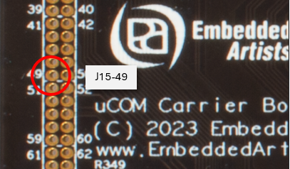
A suitable sample application is samples/basic/blinky_pwm. This application is supposed to blink an LED using the PWM API and although there isn't any LED connected to J15-49 you can use this example to test PWM. You can either connect a LED to the pin or use a logic analyzer to see the output.
west build -b ea_rt1176_kit_cm7 samples/basic/blinky_pwm