iMX6 SoloX
Hardware related
Prerequisites
To be able to follow all the instructions in this document the following is required.
- One iMX6 SoloX Developer’s Kit.
- If using the Developer’s Kit version 1 (V1) you need two FTDI cables for console output/input from both the Cortex-A7 and the Cortex-M4. Please note that only one cable is included with the Developer’s Kit V1. If you are using a Developer’s Kit version 2 (V2) you don’t need any FTDI cables.
- One Debug interface board with 10-pos FPC cable (included with Developer’s Kit). Only needed when debugging with ARM DS-5 or with Eclipse.
- Keil ULINK-Pro. Only needed when debugging with ARM DS-5.
- ARM DS-5 commercial license. Only needed when debugging with ARM DS-5.
- LPC-Link 2. Only needed when debugging using Eclipse.
UART interfaces on COM Carrier board V1
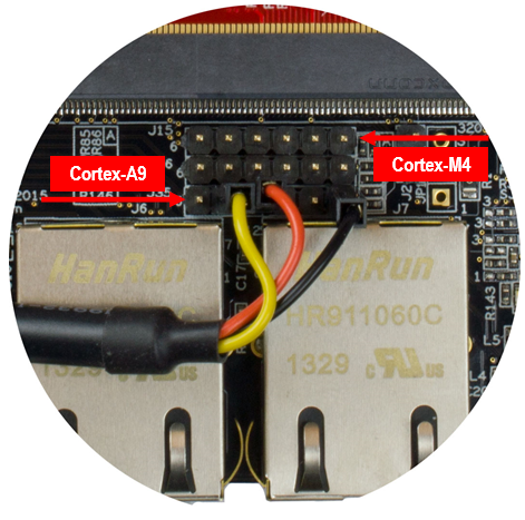
Two consoles are needed when working with both the Cortex-A7 (running Linux) and the Cortex-M4 microcontroller. Connector J35 is used by Cortex-A7 and connector J15 is used by Cortex-M4 as shown in the figure below.
Applications for Freescale Sabre Board
If you are testing pre-compiled applications developed for the Freescale Sabre board then console output will be available on different pins, that is, not on J15 connector. UART2 is used, but on pins that are available on the XBee connector (J17), see the figure below.
- Pin 4 – RX on board, TX on FTDI cable (yellow)
- Pin 9 – TX on board, RX on FTDI cable (orange)
- Pin 10 – Ground (black)
UART interfaces on COM Carrier board V2
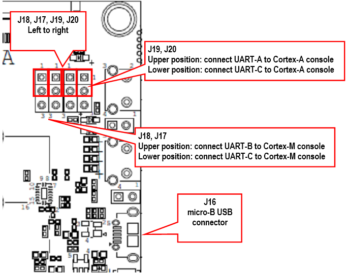
The COM Carrier board V2 has a dual channel UART-to-USB bridge, meaning that you will get two UART interfaces via one USB cable connected between the micro-B USB connector (J16) on the carrier board and your PC.
There are jumpers on the carrier board that lets you select which UART interface that is connected to the UART-to-USB bridge, see the figure below. Jumpers J19/J20 let you select between using UART-A or UART-C as console for the Cortex-A side. By default, these jumpers select the UART-A interface, that is, jumpers are in upper position. This is the position they should have for the iMX6 SoloX.
Jumpers J17/18 lets you select between using UART-B or UART-C as console for the Cortex-M side. By default, these jumpers are not inserted, but they should be in upper position for the iMX6 SoloX.
Terminal application
You need a terminal application (two instances of it to connect both to the Cortex-A side and the Cortex-M side). We recommend Tera Term, but you can use the terminal application of your choice. Connect to the virtual COM ports using 115200 as baud rate, 8 data bits, 1 stop bit, and no parity.
Download and start an application
This section describes how to download and start a pre-compiled application.
Update boot partition with needed files
The remaining parts of this chapter assumes that the first partition of the eMMC contains the pre-compile applications.
If you have programmed your board using a UUU bundle from 2020-11-06 or later the files will already have been copied to the eMMC flash. If you have programmed using an older version and don’t want to update you can follow these instructions.
It is not necessary to have the Cortex-M applications on the eMMC, but for simplicity the following instructions in this section assumes they are.
Download pre-compiled applications
Go to https://sw.embeddedartists.com and download the file compiled_cortex_m4_apps.zip.
Direct link: https://sw.embeddedartists.com/imx6sx/compiled_cortex_m4_apps.zip
Copy via USB memory stick
There are several ways to copy these pre-compiled files to the eMMC, but here we will use a USB memory stick.
-
Unpack the file
compiled_cortex_m4_apps.zipfile and copy the unpacked files to the USB memory stick. This is something you do on your computer. -
Boot into Linux and insert the USB memory stick into the USB host port on the carrier board. You will see output like below in the console when inserting the USB memory stick. The most important part is the last line that lists the device name (
sda1).[ 23.104504] usb 1-1.2: new high-speed USB device number 4 using ci_hdrc
[ 23.165591] usb 1-1.2: New USB device found, idVendor=0781, idProduct=5406, bcdDevice= 0.10
[ 23.173972] usb 1-1.2: New USB device strings: Mfr=1, Product=2, SerialNumber=3
[ 23.194511] usb 1-1.2: Product: U3 Cruzer Micro
[ 23.199055] usb 1-1.2: Manufacturer: SanDisk Corporation
[ 23.204371] usb 1-1.2: SerialNumber: 0000185A49619848
[ 23.225447] usb-storage 1-1.2:1.0: USB Mass Storage device detected
[ 23.264533] scsi host0: usb-storage 1-1.2:1.0
[ 24.315418] scsi 0:0:0:0: Direct-Access SanDisk U3 Cruzer Micro 2.18 PQ: 0 ANSI: 2
[ 24.334542] scsi 0:0:0:1: CD-ROM SanDisk U3 Cruzer Micro 2.18 PQ: 0 ANSI: 2
[ 24.345768] sd 0:0:0:0: [sda] 8015505 512-byte logical blocks: (4.10 GB/3.82 GiB)
[ 24.364543] sd 0:0:0:0: [sda] Write Protect is off
[ 24.373248] sd 0:0:0:0: [sda] No Caching mode page found
[ 24.378630] sd 0:0:0:0: [sda] Assuming drive cache: write through
[ 24.443649] sda: sda1 -
Mount the USB memory stick and eMMC partition. The USB memory stick has in this example the device name
sda1as can be seen in the output in step 2 above. The partition on the eMMC that we will use is available at/dev/mmcblk2p1.mkdir /mnt/usb
mount /dev/sda1 /mnt/usb
mkdir /mnt/mmcboot
mount /dev/mmcblk2p1 /mnt/mmcboot -
Copy the bin file(s) from the USB memory stick to the boot partition. In this example we are only copying
m4_hello_world.bin.cp /mnt/usb/m4_hello_world.bin /mnt/mmcboot/ -
Unmount the devices
umount /mnt/usb
umount /mnt/mmcboot
Change the device tree file
Some of the U-Boot environment variables need to be updated.
- You must have booted into the U-Boot console.
- Change the device tree file (dtb) to use by Linux. The example below sets the file to use for the iMX7 Dual uCOM Developer’s Kit V2. If you are using a different board just use the same name as set by default in the
fdt_filevariable and append-m4.setenv fdt_file imx6sxea-com-kit_v2-m4.dtb
saveenv
Run from QSPI
In this section the application is copied from eMMC to QSPI flash and then started.
Make sure you have built an application for QSPI or selected a pre-built application for QSPI (name ends with _qspi). The application file must have been copied to eMMC as described in the Update boot partition... section above.
- You must have booted into the U-Boot console.
- Set the M4 file name in the m4image variable.
setenv m4image m4_hello_qspi.bin - Copy the Cortex-M4 application to QSPI flash.
run update_m4_from_sd - Boot the M4 application.
run m4boot
If you have modified the m4boot variable as described in the sections below you can revert back to the default setting (for QSPI booting) by running env default -a.
Run from TCM
Make sure you have built an application for TCM or selected a pre-built application for TCM (name ends with tcm). The application file must have been copied to eMMC as described in the Update boot partition with needed files section.
- You must have booted into the U-Boot console.
- Set the M4 file name in the m4image variable.
setenv m4image m4_hello_tcm.bin - Set the address where the application will run from (TCM memory in this case).
setenv m4runaddr 0x7f8000 - Update the
m4bootvariable so it loads the image from eMMC to DDR memory, copies from DDR memory to TCM memory and then boots the application.setenv m4boot 'run loadm4image; cp.b ${loadaddr} ${m4runaddr} ${filesize}; bootaux ${m4runaddr}' - Save the changes.
saveenv - Boot the M4 application.
run m4boot
Run from OCRAM
Make sure you have built an application for OCRAM or selected a pre-built application for OCRAM (name ends with ocram). The application file must have been copied to eMMC as described in the Update boot partition with needed files section.
- You must have booted into the U-Boot console.
- Set the M4 file name in the m4image variable.
setenv m4image m4_hello_ocram.bin - Set the address where the application will run from (OCRAM memory in this case).
setenv m4runaddr 0x910000 - Update the
m4bootvariable so it loads the image from eMMC to DDR memory, copies from DDR memory to OCRAM memory and then boots the application.setenv m4boot 'run loadm4image; cp.b ${loadaddr} ${m4runaddr} ${filesize}; bootaux ${m4runaddr}' - Save the changes.
saveenv - Boot the M4 application.
run m4boot
Run from DDR RAM
Make sure you have built an application for DDR RAM or selected a pre-built application for DDR RAM (name ends with ddr). The application file must have been copied to eMMC as described in the Update boot partition with needed files section.
- You must have booted into the U-Boot console.
- Set the M4 file name in the
m4imagevariable.setenv m4image m4_hello_ddr.bin - Set the address where the application will run from (DDR memory in this case).
setenv m4runaddr 0x9ff00000 - The default
loadm4imagevariable will load to the address set inloadaddrvariable. We don’t want to setloadaddrto the same address as used by the M4 application sinceloadaddrwill also be used when loading the kernel. Instead we create a newloadm4image_ddrvariable that will load the application directly to the address where it will be started.setenv loadm4image_ddr 'fatload mmc ${mmcdev}:${mmcpart} ${m4runaddr} ${m4image}' - Update the
m4bootvariable so it loads the image from eMMC to DDR memory and then boots the application.setenv m4boot 'run loadm4image_ddr; bootaux ${m4runaddr}' - Save the changes.
saveenv - Boot the M4 application.
run m4boot
Automatically start the M4 application
If you want the M4 application to start during boot of the board follow the instructions below.
- You must have booted into the U-Boot console.
- You should also have followed the instructions in any of the sections above depending on which type of application you use.
- Change the
bootcmdvariable to first runm4bootand then boot Linux.setenv bootcmd "run m4boot; ${bootcmd}"
saveenv
Remote communication applications (RPMsg)
Ping-pong application
The RPMsg ping-pong application is an example of communication between the Cortex-A9 core and the Cortex-M4 core using the RPMsg API.
- Make sure the
m4_rpmsg_ping_qspi.binfile is available on eMMC as described in the Update boot partition with needed files section. - Follow the instruction in the Run from QSPI section for how to run an application from QSPI memory, but use the file name
m4_rpmsg_ping_qspi.bininstead ofm4_hello_qspi.bin. - In the U-Boot console add the boot argument
uart_from_osctoextra_bootargsto make Cortex-A9 and Cortex-M4 UART clocks match.setenv extra_bootargs uart_from_osc
saveenv - Boot the M4 application
run m4boot - In the console for the Cortex-M4 you will now see the output below
RPMSG PingPong FreeRTOS RTOS API Demo...
RPMSG Init as Remote - In the console for Cortex-A9 boot into Linux
boot - When Linux has booted you need to load the rpmsg pingpong module.
modprobe imx_rpmsg_pingpong - You will now see messages in both consoles / terminals.