iMX7 Dual
Hardware related
Prerequisites
To be able to follow all the instructions in this document the following is required.
- One iMX7 Dual Developer’s Kit.
- If using the Developer’s Kit version 1 (V1) you need two FTDI cables for console output/input from both the Cortex-A7 and the Cortex-M4. Please note that only one cable is included with the Developer’s Kit V1. If you are using a Developer’s Kit version 2 (V2) you don’t need any FTDI cables.
- One Debug interface board with 10-pos FPC cable (included with Developer’s Kit). Only needed when debugging with ARM DS-5 or with Eclipse.
- Keil ULINK-Pro. Only needed when debugging with ARM DS-5.
- ARM DS-5 commercial license. Only needed when debugging with ARM DS-5.
- LPC-Link 2. Only needed when debugging using Eclipse.
UART interfaces on COM Carrier board V1
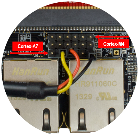
Two consoles are needed when working with both the Cortex-A7 (running Linux) and the Cortex-M4 microcontroller. Connector J35 is used by Cortex-A7 and connector J15 is used by Cortex-M4 as shown in the figure below.
UART interfaces on COM Carrier board V2
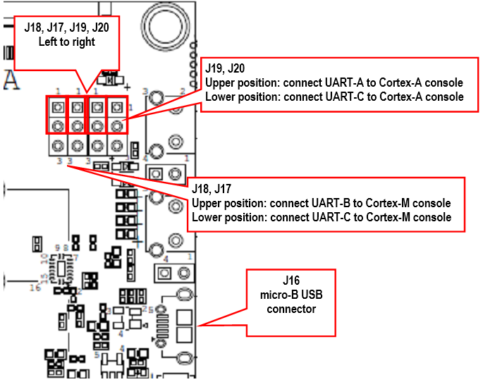
The COM Carrier board V2 has a dual channel UART-to-USB bridge, meaning that you will get two UART interfaces via one USB cable connected between the micro-B USB connector (J16) on the carrier board and your PC.
There are jumpers on the carrier board that lets you select which UART interface that is connected to the UART-to-USB bridge, see the figure below. Jumpers J19/J20 let you select between using UART-A or UART-C as console for the Cortex-A side. By default, these jumpers select the UART-A interface, that is, jumpers are in upper position. This is the position they should have for the iMX7 Dual.
Jumpers J17/18 lets you select between using UART-B or UART-C as console for the Cortex-M side. By default, these jumpers are not inserted, but they should be in upper position for the iMX7 Dual.
Terminal application
You need a terminal application (two instances of it to connect both to the Cortex-A side and the Cortex-M side). We recommend Tera Term, but you can use the terminal application of your choice. Connect to the virtual COM ports using 115200 as baud rate, 8 data bits, 1 stop bit, and no parity.
Download and start an application
This section describes how to download and start a pre-compiled application.
Update boot partition with needed files
The remaining parts of this chapter assumes that the first partition of the eMMC contains the pre-compile applications.
If you have programmed your board using a UUU bundle from 2020-11-04 or later the files will already have been copied to the eMMC flash. If you have programmed using an older version and don’t want to update you can follow these instructions.
It is not necessary to have the Cortex-M applications on the eMMC, but for simplicity the following instructions in this section assumes they are.
Download pre-compiled applications
Go to https://sw.embeddedartists.com and download the file compiled_cortex_m4_apps.zip.
Copy via USB memory stick
There are several ways to copy these pre-compiled files to the eMMC, but here we will use a USB memory stick.
-
Unpack the file
compiled_cortex_m4_apps.zipfile and copy the unpacked files to the USB memory stick. This is something you do on your computer. -
Boot into Linux and insert the USB memory stick into the USB host port on the carrier board. You will see output like below in the console when inserting the USB memory stick. The most important part is the last line that lists the device name (
sda1).[ 23.104504] usb 1-1.2: new high-speed USB device number 4 using ci_hdrc
[ 23.165591] usb 1-1.2: New USB device found, idVendor=0781, idProduct=5406, bcdDevice= 0.10
[ 23.173972] usb 1-1.2: New USB device strings: Mfr=1, Product=2, SerialNumber=3
[ 23.194511] usb 1-1.2: Product: U3 Cruzer Micro
[ 23.199055] usb 1-1.2: Manufacturer: SanDisk Corporation
[ 23.204371] usb 1-1.2: SerialNumber: 0000185A49619848
[ 23.225447] usb-storage 1-1.2:1.0: USB Mass Storage device detected
[ 23.264533] scsi host0: usb-storage 1-1.2:1.0
[ 24.315418] scsi 0:0:0:0: Direct-Access SanDisk U3 Cruzer Micro 2.18 PQ: 0 ANSI: 2
[ 24.334542] scsi 0:0:0:1: CD-ROM SanDisk U3 Cruzer Micro 2.18 PQ: 0 ANSI: 2
[ 24.345768] sd 0:0:0:0: [sda] 8015505 512-byte logical blocks: (4.10 GB/3.82 GiB)
[ 24.364543] sd 0:0:0:0: [sda] Write Protect is off
[ 24.373248] sd 0:0:0:0: [sda] No Caching mode page found
[ 24.378630] sd 0:0:0:0: [sda] Assuming drive cache: write through
[ 24.443649] sda: sda1 -
Mount the USB memory stick and eMMC partition. The USB memory stick has in this example the device name
sda1as can be seen in the output in step 2 above. The partition on the eMMC that we will use is available at/dev/mmcblk2p1.mkdir /mnt/usb
mount /dev/sda1 /mnt/usb
mkdir /mnt/mmcboot
mount /dev/mmcblk2p1 /mnt/mmcboot -
Copy the bin file(s) from the USB memory stick to the boot partition. In this example we are only copying
m4_hello_world.bin.cp /mnt/usb/m4_hello_world.bin /mnt/mmcboot/ -
Unmount the devices
umount /mnt/usb
umount /mnt/mmcboot
Change the device tree file
Some of the U-Boot environment variables need to be updated.
- You must have booted into the U-Boot console.
- Change the device tree file (dtb) to use by Linux. The example below sets the file to use for the iMX7 Dual uCOM Developer’s Kit V2. If you are using a different board just use the same name as set by default in the
fdt_filevariable and append-m4.setenv fdt_file imx7dea-ucom-kit_v2-m4.dtb
saveenv
Run from TCM
Make sure you have built an application for TCM or selected a pre-built application for TCM (name ends with tcm). The application file must have been copied to eMMC as described in the Update boot partition with needed files section.
- You must have booted into the U-Boot console.
- Set the M4 file name in the m4image variable.
setenv m4image m4_hello_tcm.bin - Set the address where the application will run from (TCM memory in this case).
setenv m4runaddr 0x7f8000 - Update the
m4bootvariable so it loads the image from eMMC to DDR memory, copies from DDR memory to TCM memory and then boots the application.setenv m4boot 'run loadm4image; cp.b ${loadaddr} ${m4runaddr} ${filesize}; bootaux ${m4runaddr}' - Save the changes.
saveenv - Boot the M4 application.
run m4boot
Run from OCRAM
Make sure you have built an application for OCRAM or selected a pre-built application for OCRAM (name ends with ocram). The application file must have been copied to eMMC as described in the Update boot partition with needed files section.
- You must have booted into the U-Boot console.
- Set the M4 file name in the m4image variable.
setenv m4image m4_hello_ocram.bin - Set the address where the application will run from (OCRAM memory in this case).
setenv m4runaddr 0x910000 - Update the
m4bootvariable so it loads the image from eMMC to DDR memory, copies from DDR memory to OCRAM memory and then boots the application.setenv m4boot 'run loadm4image; cp.b ${loadaddr} ${m4runaddr} ${filesize}; bootaux ${m4runaddr}' - Save the changes.
saveenv - Boot the M4 application.
run m4boot
Run from DDR RAM
Make sure you have built an application for DDR RAM or selected a pre-built application for DDR RAM (name ends with ddr). The application file must have been copied to eMMC as described in the Update boot partition with needed files section.
- You must have booted into the U-Boot console.
- Set the M4 file name in the
m4imagevariable.setenv m4image m4_hello_ddr.bin - Set the address where the application will run from (DDR memory in this case).
setenv m4runaddr 0x9ff00000 - The default
loadm4imagevariable will load to the address set inloadaddrvariable. We don’t want to setloadaddrto the same address as used by the M4 application sinceloadaddrwill also be used when loading the kernel. Instead we create a newloadm4image_ddrvariable that will load the application directly to the address where it will be started.setenv loadm4image_ddr 'fatload mmc ${mmcdev}:${mmcpart} ${m4runaddr} ${m4image}' - Update the
m4bootvariable so it loads the image from eMMC to DDR memory and then boots the application.setenv m4boot 'run loadm4image_ddr; bootaux ${m4runaddr}' - Save the changes.
saveenv - Boot the M4 application.
run m4boot
Automatically start the M4 application
If you want the M4 application to start during boot of the board follow the instructions below.
- You must have booted into the U-Boot console.
- You should also have followed the instructions in any of the sections above depending on which type of application you use.
- Change the
bootcmdvariable to first runm4bootand then boot Linux.setenv bootcmd "run m4boot; ${bootcmd}"
saveenv
Remote communication applications (RPMsg)
Ping-pong application
The RPMsg ping-pong application is an example of communication between the Cortex-A7 core and the Cortex-M4 core using the RPMsg API.
- Make sure the
m4_rpmsg_ping_tcm.binfile is available on eMMC as described in the Update boot partition with needed files section. - Follow the instruction in the Run from TCM section for how to run an application from TCM memory, but use the file name
m4_rpmsg_ping_tcm.bininstead ofm4_hello_tcm.bin. - In the U-Boot console add the boot argument
uart_from_osctoextra_bootargsto make Cortex-A7 and Cortex-M4 UART clocks match.setenv extra_bootargs uart_from_osc
saveenv - Boot the M4 application
run m4boot - In the console for the Cortex-M4 you will now see the output below
RPMSG PingPong FreeRTOS RTOS API Demo...
RPMSG Init as Remote - In the console for Cortex-A7 boot into Linux
boot - When Linux has booted you need to load the rpmsg pingpong module.
modprobe imx_rpmsg_pingpong - You will now see messages in both consoles / terminals.
TTY application
The RPMsg TTY application is an example of communication between the Cortex-A7 core and the Cortex-M4 core using the RPMsg API. A TTY channel will be setup making it possible to send messages from the Cortex-A7 core to the Cortex-M4 core from Linux user-space.
- Make sure the
m4_rpmsg_echo_tcm.binfile is available on eMMC as described in the Update boot partition with needed files section. - Follow the instruction in the Run from TCM section for how to run an application from TCM memory, but use the file name
m4_rpmsg_echo_tcm.bininstead ofm4_hello_tcm.bin. - In the U-Boot console add the boot argument
uart_from_oscto extra_bootargs to make Cortex-A7 and Cortex-M4 UART clocks match.setenv extra_bootargs uart_from_osc
saveenv - Boot the M4 application
run m4boot - In the console for the Cortex-M4 you will now see the output below
RPMSG String Echo FreeRTOS RTOS API Demo...
RPMSG Init as Remote - In the console for Cortex-A7 boot into Linux
boot - When Linux has booted you need to load the rpmsg tty module. You will see a confirmation that a channel has been created (similar as below).
modprobe imx_rpmsg_tty[ 23.739119] imx_rpmsg_tty virtio0.rpmsg-openamp-demo-channel.-1.0: new channel: 0x400 -> 0x0!
[ 23.757228] Install rpmsg tty driver! - In the console for the Cortex-M4 you will see output similar to below when the module is loaded.
Name service handshake is done, M4 has setup a rpmsg channel [0 ---> 1024] - From Linux you can now send a message to the Cortex-M4 side by using the new TTY channel (
dev/ttyRPMSG0)echo hello > /dev/ttyRPMSG0
FreeRTOS
NXP has developed a number of sample applications and peripheral drivers for the Cortex-M4 bundled together with the real-time operating system FreeRTOS.
Installation
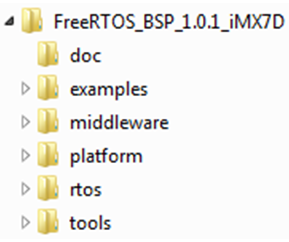
The bundle can be downloaded from NXP’s website. When writing these instructions the version of the bundle was v1.0.1. Follow the link below to download the bundle. https://www.nxp.com/webapp/Download?colCode=FreeRTOS_iMX7D_1.0.1_WIN
You need to register an account at nxp.com in order to get access to the FreeRTOS installation package.
Build with ARM DS-5
This section describes how to setup ARM DS-5 to build the sample applications. The instructions are originally from the document found at the location below (<FreeRTOS> is the path to where the FreeRTOS bundle was installed).
<FreeRTOS>\doc\ Getting_Started_with_FreeRTOS_BSP_for_i.MX_7Dual.pdf.
You need a commercial license in order to run ARM DS-5 and you must also have installed ARM DS-5 before following the instructions.
-
Start ARM DS-5
-
Import an application
-
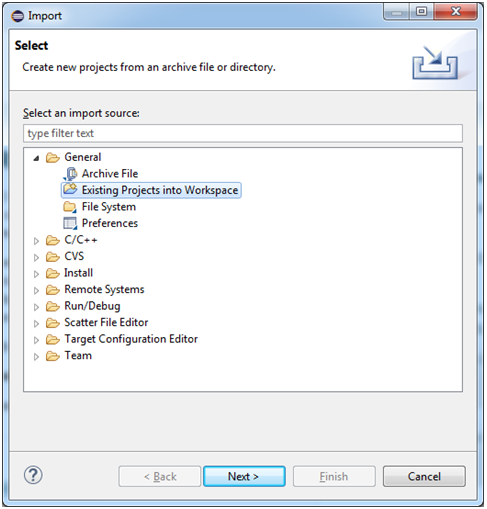
Go to File > Import > General > Existing Projects into Workspace and click the Next button as shown the figure below.
-
b. Browse to the DS-5 project files for the application to import. In this example it is the OCRAM version of
hello worldfound at:<FreeRTOS>\examples\imx7d_sdb_m4\demo_apps\hello_world_ocram\ds5
-
-
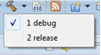
Choose build target by clicking on the arrow to the right of the hammer in to toolbar, see the figure below. When the target has been selected the project will be built. If target has previously been selected it is enough to click on the hammer icon.
-
The built application is now available at the location below. There will be both an
axffile and abinfile. It is thebinfile that should be loaded to the iMX7 Dual Board as described in the Download and start an application section.<FreeRTOS>\examples\imx7d_sdb_m4\demo_apps\hello_world_ocram\ds5\debug
Debug using DS-5
With ARM DS-5, a Keil ULINK Pro, and a debug interface board it is possible to download and debug an application on the Cortex-M4.
Setup the hardware
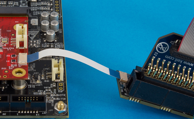
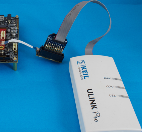
The next two figures below show how the ULINK Pro and debug interface board is connected to the iMX7 Dual uCOM Board.
Import OCRAM version of hello world
The application is downloaded and debugged from internal RAM, i.e., OCRAM. Follow the steps in the Build with Arm DS-5 section to import the hello world application.
Create and Debug configuration
To be able to download and debug a Debug configuration must be created.
-
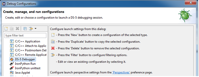
Go to Run > Debug Configurations and select DS-5 Debugger as shown in the figure below.
-
Right click on DS-5 Debugger and select New.
-
Give the configuration a name such as iMX7 Cortex-M4 and then select the Connection tab as shown in the figure below.
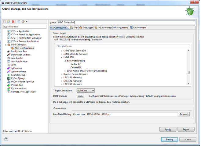
-
In the Connection tab go to NXP > i.MX7 SDB > Bare Metal debug and choose Debug Cortex-M4 as shown in the figure above.
-
Still in the Connection tab select ULINKpro in the Target Connection list and then click the Browse button in the Connections section. Select the ULINKpro connection.
notePlease note that the ULINK pro debug adapter must be connected to your computer before clicking the "Browse" button
-
Click on the Files tab and then the Workspace button. Select the
axffile in the debug folder as shown in the figure below.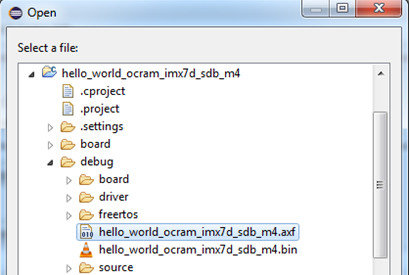
-
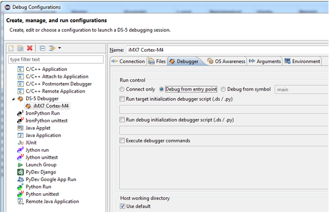
Go to the Debugger tab and select Debug from entry point as shown in the figure below.
-
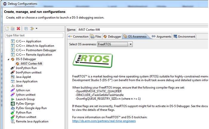
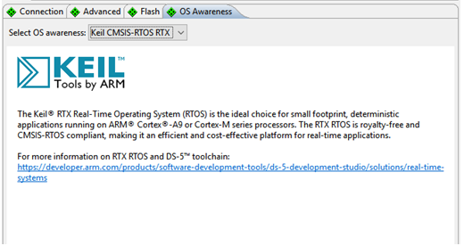
Go to the OS Awareness tab and choose FreeRTOS in the list as shown in the figure below.
-
Click the Apply button and then the Debug button to initiate a debug session. When the application has been downloaded to the target it could look like the figure below.
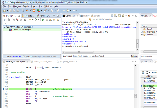
If you are not able to start the debug session please make sure that you have only booted into U-Boot on the Cortex-A7 and not into Linux when you start the debug session.
If the terminal/console attached to the A9-core (Linux) seem to be unresponsive, that is, it doesn’t accept any input please read the Linux terminal doesn't accept... section.
Build with Arm GCC
Install ARM GCC
Download and install GCC ARM Embedded. The file gcc-arm-none-eabi-4_8-2014q1-20140314-win32.exe was used when writing these instructions.
https://launchpad.net/gcc-arm-embedded/+download
Install MinGW
MinGW – native Windows port of the GNU Compiler Collection (GCC) is also needed to build the applications on a Windows machine.
-
Go to the link below and click the Download button http://sourceforge.net/projects/mingw/
-
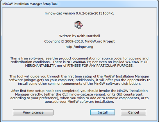
Start the downloaded installation file and click the Install button and then click the Continue button on the dialog windows that will appear.
-
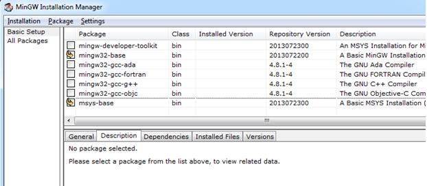
When the installation manager window appears, as shown in the figure below, choose mingw32-base and msys-base in the Basic Setup section.
-
Click Installation > Apply Changes for the packages to be installed.
-
When the installation has finished add
C:\MinGW\bin(if this is where you installed MinGW) to thePATHvariable. There are several ways to add something to thePATHvariable.- In a command prompt write
set PATH=%PATH%;C:\MinGW\bin - To permanently add MinGW to
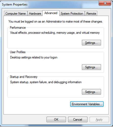
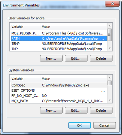
PATHopen System properties by (this applies for Windows 7) right clicking on Computer in an Explorer window and then select Properties. Click Change settings and then the Advanced tab as shown in the figure below. Click on the Environment Variables button and edit thePATHvariable as shown in the second figure below.
- In a command prompt write
-
Create the
ARMGCC_DIRenvironment variable- Click the New button below System variables as seen in the figure above.
- Add
ARMGCC_DIRas variable name and specify the path to ARM GCC as value. The default installation path of ARM GCC which has been installed when following these instructions is:
C:\Program Files (x86)\GNU Tools ARM Embedded\4.8 2014q1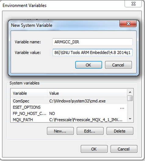
-
Click OK and then OK again.
Install CMake
Download and install CMake from the link below. Make sure to add CMake to the system path as shown in the figure below.
http://www.cmake.org/cmake/resources/software.html

Build Application
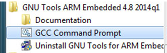
-
Open a GCC Command prompt. When ARM GCC was installed a shortcut was created in the start menu as shown in the figure below.
-
Change directory to the application that should be built. In this example the hello_world application is built.
cd <FreeRTOS>\examples\imx7d_sdb_m4\demo_apps\hello_world\armgcc
- Run
build_debug.batto build the application - The output of the build will be both an
elffile and abinfile located in the sub-directorydebug. Use the instructions in the Download and start an application section to download the application to the board.
Build with Eclipse and Arm GCC
How to install and use ARM GCC from the command line is described in section 6.4 above. Most often you however need to use a development environment (editor) when developing an application. This section will describe how you can setup Eclipse to use ARM GCC when developing the application.
You must have followed the instructions in the Build with Arm GCC section before continuing with the instructions in this section.
It is assumed that you have installed Eclipse with the CDT (C/C++ Development Tooling) plugin. Eclipse version 4.4.2 (Luna) and CDT 8.6.0 were used when writing these instructions.
Install GNU ARM Eclipse plugins
We will utilize CDT extensions called GNU Arm Eclipse. Follow the instructions on the link below to install these extensions/plugins.
http://gnuarmeclipse.github.io/plugins/install/
Create project: New
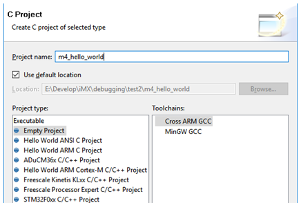
Start by creating a new C Project. Go to File > New Project and then select C Project under the C/C++ group as shown in the figure below.
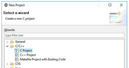
Click Next, select Empty Project, Cross ARM GCC as toolchain and give the project a name as shown in the figure below.
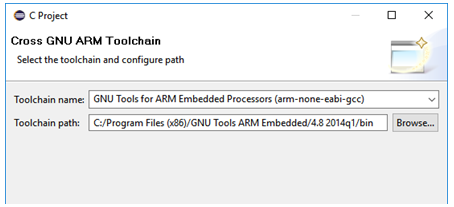
Click Next and then Next again. The toolchain and path should be selected. If GNU Tools hasn’t been selected by default change to this as shown in the figure below.
Create project: Linked folders
The source code that we need to build is located in several different folders and we need to add these to the Eclipse project. There are several ways to do this, but in this example we will use linked folders and keep the structure created when installing the bundle.
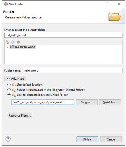
Begin by adding a linked folder to the demo application. In this example we will be using the hello_world demo. Click on the Add Folder icon in the toolbar as shown in the figure below. Then select Folder. An alternative way is to do this from the menu: File > New > Folder.

In the dialog window click on the Advanced button and then to Link to alternate location and browse to the <FreeRTOS path>/examples/imx7d_sdb_m4/demo_apps/hello_world folder. This is shown in the figure below.
Repeat the above steps for the following folders:
<FreeRTOS path>/examples/imx7d_sdb_m4- This folder contains board specific code
<FreeRTOS path>/platform- Contains initialization and driver code for the iMX7 processor
<FreeRTOS path>/rtos/FreeRTOS- The FreeRTOS code
When all folders have been added to the project it will look like in the figure below.

Create project: Exclude from build
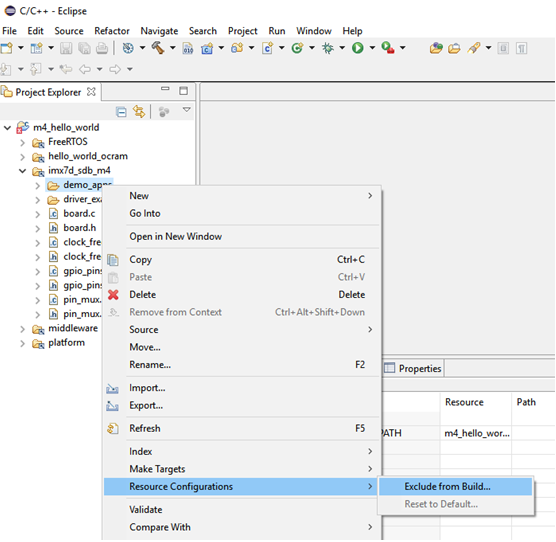
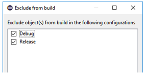
Some of the sub-folders added to project as described in the section above shouldn’t be part of the build. These can be excluded by right-clicking on the folder and then selecting Resource Configurations" > Exclude from Build. This is shown in the figure below.
We must also specify which configurations to exclude the folders from. In our case we select both Debug and Release as shown in the figure below.
Exclude all the following files and folders:
imx7d_sdb_m4/demo_apps- The
demo_appsfolder contains several applications. We only want to buildhello_world.
- The
imx7d_sdb_m4/driver_examples- The
driver_examplesfolder contains several applications. We only want to buildhello_world.
- The
FreeRTOS/Source/portable/IAR- This folder contains code specific for the IAR compiler
FreeRTOS/Source/portable/RVDS- This folder contains code specific for the RVDS compiler
FreeRTOS/Source/portable/MemMang/heap_2.c(alsoheap_3.candheap_4.c)- The
MemMangfolder contains several implementations of memory allocation routines. We can only use one and will keep the one implemented inheap_1.c. Exclude all other files.
- The
platform/CMSIS/DSP_Lib
Create project: Include paths
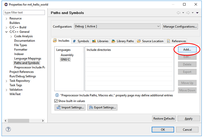
Header files are located at several different locations in this project structure. These header files must be found during a build. This can be done by right-clicking on the project and then select Properties. Go to C/C++ General > Paths and Symbols. Select GNU C as language and then click the Add button as shown in the figure below.
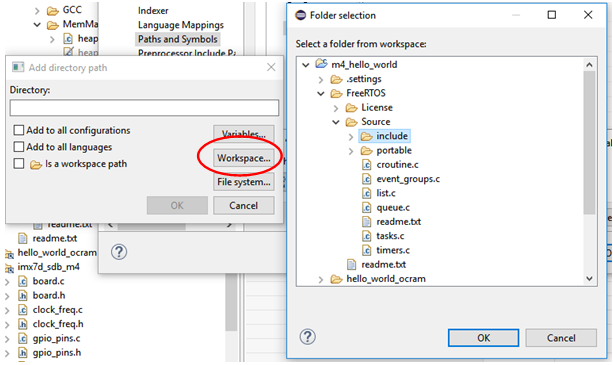
We are going to add the paths as relative to the workspace so click in the Workspace button and then browse to the folder to include. In the figure below it is shown how the include folder for FreeRTOS is selected.
Add the following folders as include paths:
FreeRTOS/Source/includeFreeRTOS/Source/portable/GCC/ARM_CM4Fhello_worldimx7d_sdb_m4platform/CMSIS/Includeplatform/devicesplatform/devices/MCIMX7D/includeplatform/devices/MCIMX7D/startupplatform/devices/drivers/incplatform/devices/utilities/inc
Create project: Settings
There are several project settings that must be updated. Right click on the project and then select Properties.
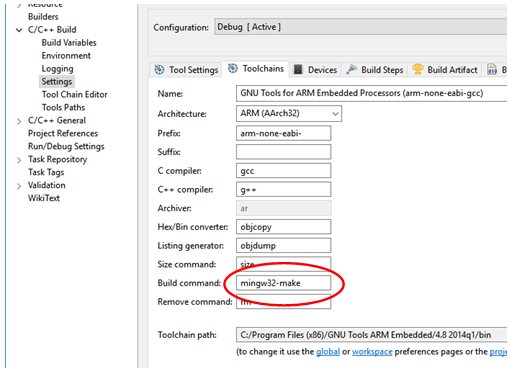
By default, make is used to build the application, but since we have installed mingw make we need to do an update to the toolchain setting. Go to C/C++ build > Settings and click on the Toolchains tab as shown in the figure below. Change the value of the Build command field from make to mingw32-make.
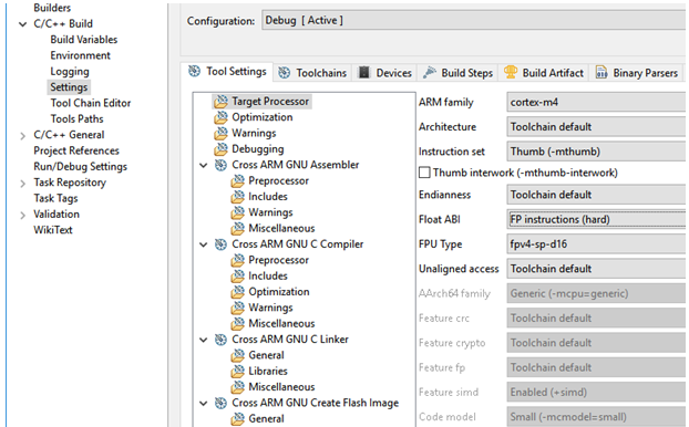
Go to the Tool Settings tab and click on Target Processor. Change the values of the following fields. This is also shown in the figure below.
- ARM family = cortex-m4
- Float ABI = FB instructions (hard)
- FPU Type = fpv4-sp-d16
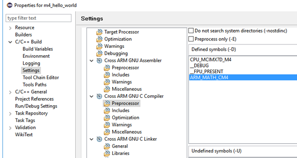
Still in the Tool Settings tab go to Cross ARM GNU C Compiler > Preprocessor. Add the symbols below:
CPU_MCIMX7D_M4__DEBUG__FPU_PRESENTARM_MATH_CM4
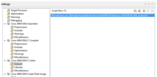
Still in the Tool Settings tab go to Cross ARM GNU C Linker > General. Add the workspace path to the linker file that is going to be used. Since we are building an application for OCRAM we select platform/devices/MCIMX7D/linker/gcc/MCIMC7D_M4_ocram.ld.
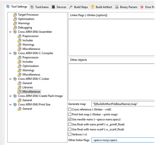
Still in the Linker group select Miscellaneous. Check the Use newlib-nano checkbox and enter -specs=nosys.specs in the Other linker flags field. These settings are shown in the figure below.
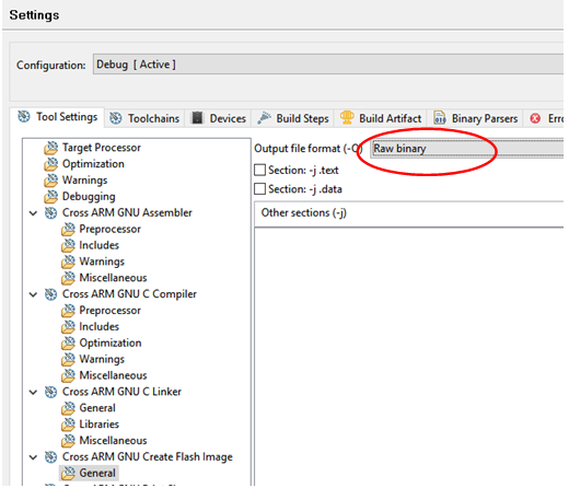
In the Tool Settings tab go to Cross ARM GNU Create Flash Image. Change output format to Raw binary.
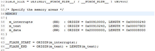
Update linker file and build application
The default setting in the linker file doesn’t match the other instructions in this document. We need to change the memory area in the linker file. Open the file platform/devices/MCIMX7D/linker/gcc/MCIMC7D_M4_ocram.ld and go to the section called MEMORY. Change m_interrupts to 0x00910000 and m_text to 0x00910240 as shown in the figure below.
Now it is time to build the application. This can, for example, be done by clicking on the Build icon in the toolbar as shown in the figure below. It can also be done by right-clicking on the project and then click on Build Project.
![]()
When the application has been built there will be a binary file in the project’s Debug folder. Use the instructions in the Run from OCRAM section to run this application on target. It is also possible to download and debug the application by following the instructions in the Debug using Eclipse section below.
Debug using Eclipse
Before following the instructions in this section, you must have followed the instructions in the Build with Eclipse and Arm GCCsection and being able to build an application.
LPC-Link 2 with J-Link firmware
We are going to use an LPC-Link 2 with Segger’s J-Link firmware as debug adapter. Follow the instructions on the link below to prepare an LPC-Link 2 with the J-Link firmware.
Instructions: https://www.segger.com/lpc-link-2.html
LPC-Link 2: https://www.embeddedartists.com/products/lpc-link2/
J-Link GDB Server
Segger’s J-Link GDB Server is used when debugging the target. Download and install the "J-Link Software and Documentation Pack". This package contains the GDB server.
https://www.segger.com/downloads/jlink
J-Link script files
A script file is needed when connecting to the M4 core using J-Link. Segger has published script files for both the A7 cores and M4 core. You need to download at least the script file for the M4 core.
Connect LPC-Link 2 to the board
Begin by connecting the LPC-Link 2 to the Debug interface board as shown in the figure below.
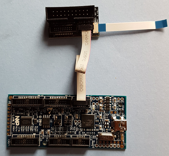
Connect the FPC cable for the Debug interface board to the connector on the COM Board as shown in the figure below.
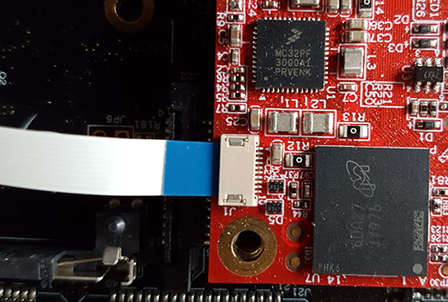
Also make sure that the LPC-Link 2 board is connected to your PC via a USB cable.
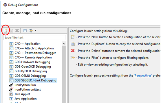
Create a debug configuration
In Eclipse go to Run > Debug Configurations and then select GDB SEGGER J-Link Debugging. Create a new launch configuration by clicking on the icon shown in the figure below.
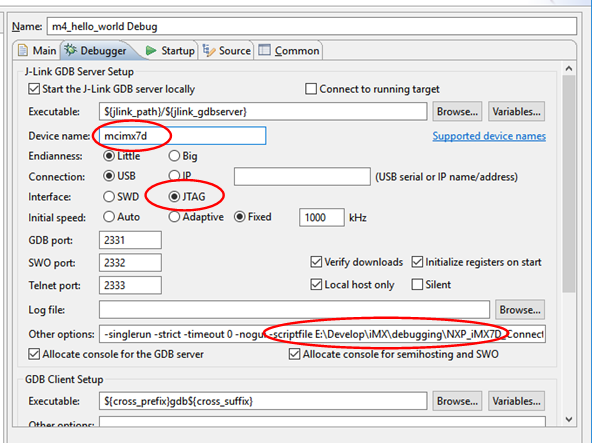
Go to the Debugger tab. When writing these instructions there was no support for iMX7 Dual devices, but device name must be specified in order to use the debug configuration.
- Enter
mcimx7das device name. - Select JTAG as interface
- In the Other options field add
-scriptfileand the path to the script file downloaded in the J-Link script files section above.
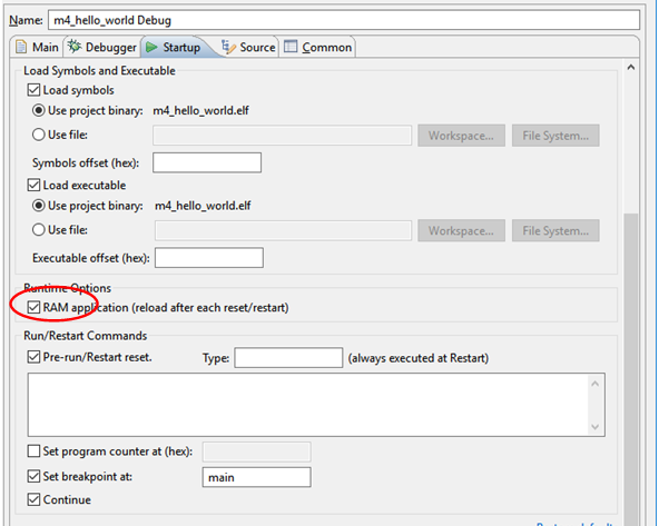
Go to the Startup tab and then Runtime Options. Select *"RAM application as shown in the figure below.
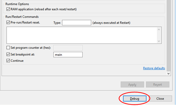
Start a debug session
There are several ways to start a debug session. One way is to click on the Debug button if the Debug configurations window is still open as shown in the figure below.
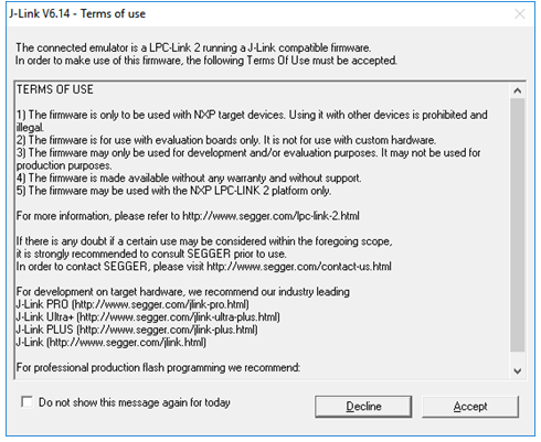
When starting the debug session, the J-Link terms and conditions must be accepted by clicking the Accept button.
Since we haven’t specified a correct device we have to select which target to debug. Select a generic Cortex-M4 as shown in the figure below.
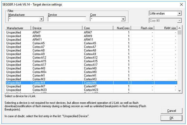
Click OK and the debug connection will be established.
We have seen that you might have to start an application on the Cortex-M4 before being able to debug a new application. Follow the instructions in the Run from TCM section to start an application.
One thing we have seen when debugging is that the second time you establish a debug session you can get a strange behaviour. The debug session will halt in the main function and you can single step, but when the FreeRTOS scheduler is started you end up in the prvPortStartFirstTask function and won’t get out of this function. When writing these instructions we don’t know the reason why this happens. The workaround is to reset the board between debug sessions.
Build with IAR Embedded Workbench
The FreeRTOS bundle contains project files for IAR Embedded Workbench and the documentation also contains instructions.
Embedded Artists has not tested the project files or documentation for IAR Embedded Workbench
Use DS-MDK for application development
DS-MDK is a commercial Eclipse based IDE and debugger from ARM/Keil. The development environment comes with support for NXP’s application processors and especially those supporting Heterogeneous Multi-Processing such as the i.MX7 Dual.
http://www2.keil.com/mdk5/ds-mdk/
This section describes how to install and use DS-MDK. The instructions are based on the document "Getting Started with DS-MDK" from ARM.
https://armkeil.blob.core.windows.net/product/gs_DS-MDK_5_24_2_en_rev3.pdf
Installation
Begin by installing MDK ARM. You will find the installer and instructions on the link below. Please note that MDK exists in a limited evaluation version, but it is a commercial product so if you want to continue to use it you need to buy a license.
https://www.keil.com/demo/eval/arm.htm
When MDK ARM has been installed download and install DS-MDK. Installer and instructions are available on the link below.
http://www2.keil.com/mdk5/ds-mdk/install/
When you start DS-MDK you have to specify where you installed MDK ARM and also choose a workspace directory for your project.
Package Manager
DS-MDK comes with a package manager that lets you install drivers and example programs for a specific device.
Open the Pack Manager by going to Window > Perspective > Open Perspective > CMSIS Pack Manager in the menu.
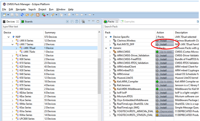
In the Pack Manager, go to NXP > i.MX 7 Series and then i.MX 7Dual. In the Packs view click on the Install button for the Keil iMX7D_DFP package as shown in the figure below.
When beginning with the application development it is recommended to use one of the existing example applications as a starting point. We are going to use the RPMSG TTY examples, that is, an application that show how to communicate between a Linux application running on the A7 core and an application running on the M4 core.
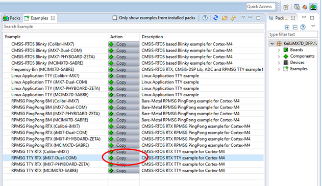
Go to the Examples tab in the Pack manager and then click on the Copy button for the RPMSG TTY RTX (iMX7-Dual-COM) example as shown in the figure below.
The application will now be added to your workspace. Go back to the Pack Manager and click on the Copy button for the Linux Application TTY (iMX7-Dual-COM). Now you have both the application that will run on the A7 core and the application that will run on the M4 core in your workspace.
Debug the M4 application
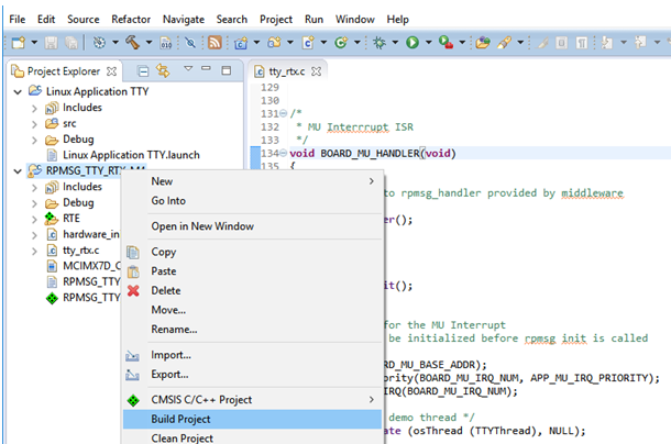
Build the application
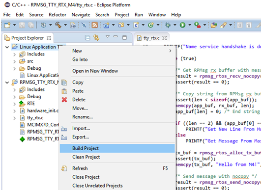
First build the application. Right-click on the RPMSG project and select Build Project as shown in the figure below.
Setup the debug adapter
A debug adapter must be connected to the board before the application can be debugged. The Setup the hardware section shows how ULINKpro is connected to the board. We recommend ULINKpro, but have also tested an LPC-Link 2 with CMSIS-DAP firmware.
Create a debug configuration
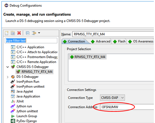
Go to Run > Debug configurations in the menu. There should be a debug configuration called RPMSG_TTY_RTX_M4 under the CMSIS DS-5 Debugger as shown in the figure below.
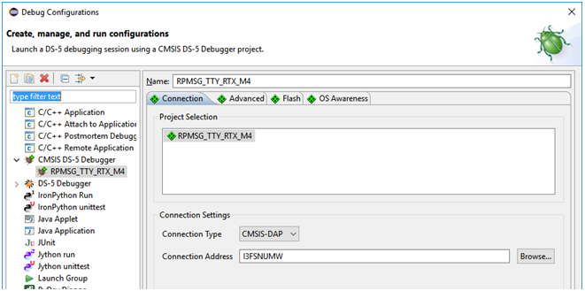
Click on the Connection tab and choose Connection Type. In the figure above a CMSIS-DAP-enabled LPC-Link 2 has been connected to the board. You have to select the debug adapter you are using and then click on the Browse button to find the actual connection (the adapter must be connected to your computer). When writing these instructions the following debug adapter types could be used.
- DSTREAM
- ULINKpro
- CMSIS-DAP
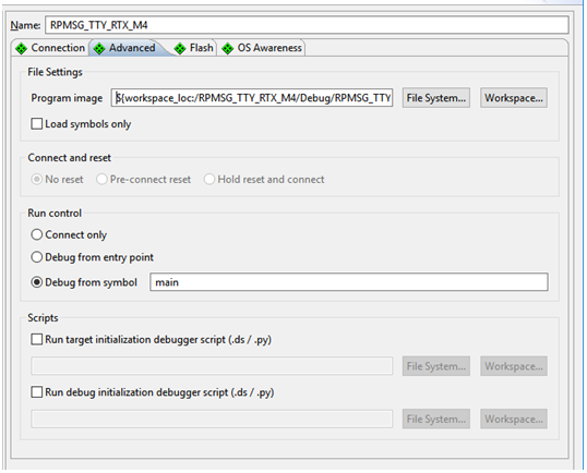
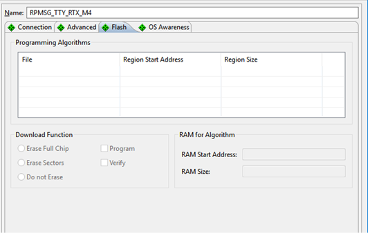
The default settings were used for all other settings. Below are screen shots for the other tabs.
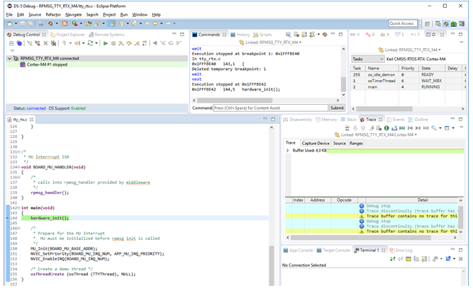
When the debug configuration is ready click on the Debug button and a debug session will be established as shown in the figure below.
Make sure that you have only booted into U-Boot on the Cortex-A7 and not into Linux. See the Simultaneous Debugging section for information about simultaneous debugging of Cortex-M4 and Cortex-A7.
Debug the Linux application
The Linux application will be debugged using gdbserver over a network connection. This means that there is no need to use the debug adapter (such as ULINKpro) when debugging the Linux application. It is however necessary to have the board connected to the same network as your development computer.
Build the application
First build the application. Right-click on the Linux Application TTY project and select Build Project as shown in the figure below.
Setup Remote System Explorer (RSE)
First get the IP address of the board. You can get this by using the ifconfig utility as shown below via a terminal application connected to the board.
ifconfig
eth0      Link encap:Ethernet  HWaddr CA:71:64:BD:1A:20
          inet addr:192.168.1.72  Bcast:192.168.1.255  Mask:255.255.255.0
          inet6 addr: fe80:
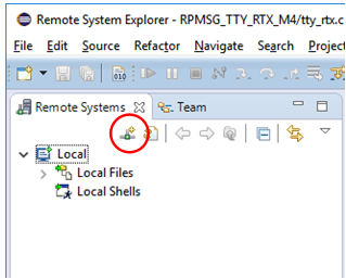
In DS-MDK, go to Window > Perspective > Open Perspective > Other and then Remote System Explorer. Click on the icon shown in the figure below to create a connection.
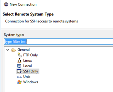
Choose SSH Only as connection type as shown in the figure below and then click Next.
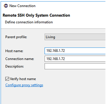
Enter the IP address in the Host name field as shown in the figure below and then click Finish to create the connection.
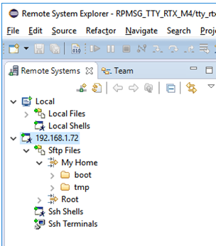
It could now look like in the figure below. If you click on Sftp Files > My Home you will see the home directory on the target. You will be asked to enter the user name (root) and password (pass) to login.
By default, root is not permitted to login over SSH. Read the Allow user root to use an SSH connection section for a solution to this problem.
Create Debug Configuration
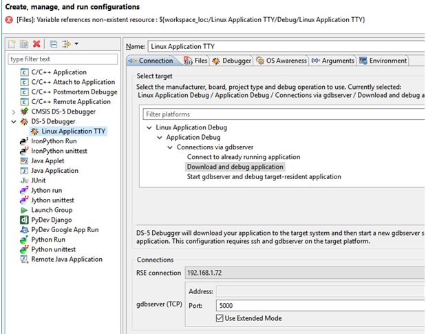
Go to Run > Debug configurations in the menu. There should be a debug configuration called Linux Application TTY under the DS-5 Debugger as shown in the figure below. Click on this configuration and go to the Connection tab. Select Download and debug application and make sure the RSE connection we created earlier is used under Connections.
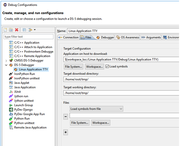
Go to the Files tab and select download and working directory. In this example we are using /home/root/tmp as shown in the figure below.
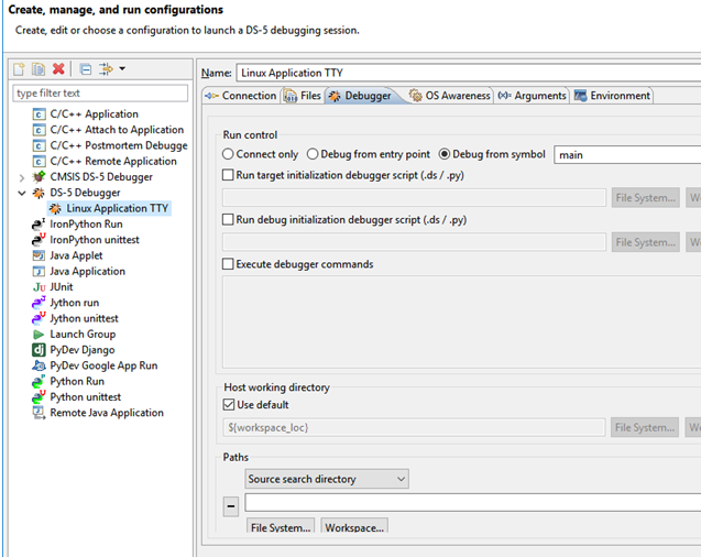
In the Debugger tab make sure Debug from symbol is chosen and the symbol is set to main as shown in the figure below.
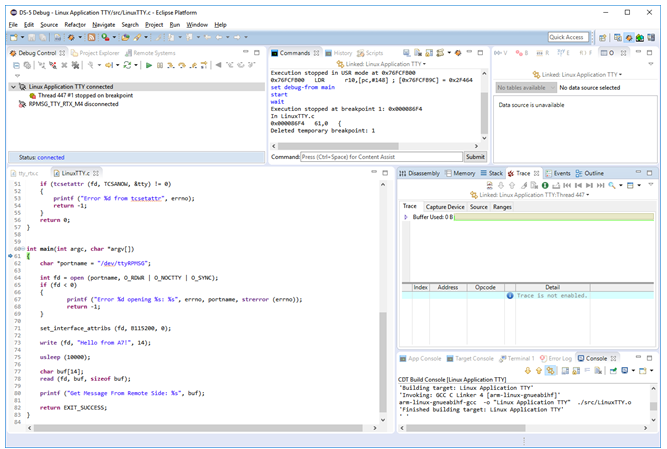
Click on the Debug button to start the debug session.
Simultaneous Debugging
Follow these steps to simultaneously debug RPMSG_TTY_RTX_M4 and Linux Application TTY.
- Boot into U-Boot
- Change device tree file (
dtb) file
setenv fdt_file imx7dea-com-kit-m4.dtb
saveenv
- Now start the debug session of
RPMSG_TTY_RTX_M4as described in the Debug the M4 application section above. - It is not possible to interact with U-Boot while
RPMSG_TTY_RTX_M4is halted until RDC has been initialized. RDC will be initialized inBOARD_RdcInitwhich is called fromhardware_init. Let at least the call to the functionhardware_initexecute and you will be able to interact with U-Boot. - Enter
bootin the U-Boot console to boot Linux
boot
- To be able to use the RPMsg TTY channel a kernel module must be loaded. When Linux has booted run the following:
modprobe imx_rpmsg_tty
imx_rpmsg_tty rpmsg0: new channel: 0x400 -> 0x0!
Install rpmsg tty driver!
- You can double-check that the module has been loaded by using
lsmod.
lsmod
Module                  Size  Used by
imx_rpmsg_tty           3418  0
...
- When the module has been loaded, start the debug session of the Linux application as described in the Debug the Linux application section above.
- You should now be able to debug the Linux application, for example, single step and when a message is sent to the M4 application the M4 debug session should halt on the breakpoint at
rpmsg_rtos_recv_nocopy.
Additional documentation
This section contains links to documentation related to heterogeneous multiprocessing.
Getting started with Multicore Programming for iMX6 SoloX
https://community.nxp.com/docs/DOC-329540
FTF: i.MX6 SoloX Heterogeneous Multiprocessing
https://community.nxp.com/pwmxy87654/attachments/pwmxy87654/imx-processors/80806/1/FTF-DES-F1132.pdf
i.MX Linux Reference Manual
There is a chapter about Remote Processor Messaging (RPMsg)
https://www.nxp.com/docs/en/reference-manual/IMX_REFERENCE_MANUAL.pdf
Troubleshooting
Allow user root to use an SSH connection
By default, the user root is not permitted to login via an SSH connection. By following these instructions root will be permitted to login through an SSH connection. It is, however, not recommended to use on a final application, but during development it can be permitted.
- Open the configuration file for the SSH server
nano /etc/ssh/sshd_config
- Find the line that starts with
#PermitRootLoginand remove the#(hash) character. If you cannot find this line just add it to the file (without the hash)
PermitRootLogin yes
- Save the file and exit the editor (in nano it is Ctrl-X followed by Y and Enter).
- Restart the SSH server
/etc/init.d/sshd restart
LPC-Link 2 with CMSIS-DAP Firmware
Install the Firmware
If you cannot install CMSIS-DAP firmware on the LPC-Link 2 follow these instructions.
- Download and install LPCScrypt from NXP
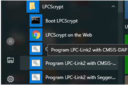
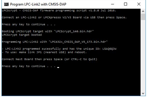
http://www.nxp.com/products/software-and-tools/software-development-tools/software-tools/lpc-microcontroller-utilities/lpcscrypt-v1.8.0:LPCSCRYPT 2. Open JP1 jumper on the LPC-Link 2 and connect the board to your computer 3. From the LPCScrypt installation run Program LPC-Link2 with CMSIS-DAP.
- A command prompt will appear. Press on a key on your keyboard to start programming the board. It will look like the figure below if programming starts and is successful.
- Close JP1 jumper on the LPC-Link 2 and power-cycle the board (remove the USB cable and insert it again).
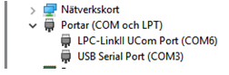
- Open the device manager and make sure the LPC-Link 2 shows up under ports as shown in the figure below. If it doesn’t appear correctly, please follow the instructions in the LPC-Link 2 doesn't enumerate... section below for a possible solution
LPC-Link 2 doesn’t enumerate with CMSIS-DAP Firmware
If LPC-Link 2 doesn’t enumerate correctly please follow the instructions on the link below. Most often the problem is related to the driver not being installed.
https://community.nxp.com/thread/389044
Driver package:
Cannot find LPC-Link 2 in DS-MDK
If you cannot find LPC-Link 2 when clicking Browse in the Connection Settings first try to connect the LPC-Link 2 to a USB2 port instead of a USB3 port (if available). If this doesn’t help try to locate the debug adapter using Keil uVision 5 (installed when installing MDK ARM).
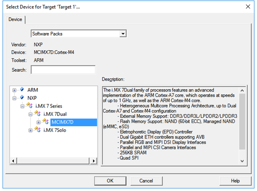
- Create a project and select an iMX 7Dual device in the package manager as shown in the figure below.
- Right-click on the created project and select Options for Target as shown in the figure below.

- Go to the Debug tab and select CMSIS-DAP Debugger as shown in the figure below.
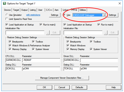
- Click on the Settings button and look for the Serial No field as shown in the figure below.
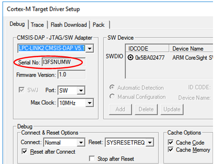
- Copy this serial number and enter it into the Connection Address field in DS-MDK as shown in the figure below.
Linux (A7) terminal/console doesn’t accept input while debugging M4
When you are debugging the M4-core and more specifically when you have halted the M4-core from within the debugger it can seem as the Linux terminal/console is unresponsive (doesn’t accept any input).
Solution
First, make sure you have updated U-Boot and Linux to the 4.1.15_2.0.0 version or later. In this release U-Boot will make some RDC initialization that solves part of this problem.
Secondly your M4-application must have assigned the M4 to domain 1 as shown below.
RDC_SetDomainID(RDC, rdcMdaM4, BOARD_DOMAIN_ID, false);
If you are using the example code from NXP this call is being made in board.c > BOARD_RdcInit. BOARD_RdcInit is called from hardware_init.c > hardware_init.