iMX8M
Hardware
- COM Carrier Board V2
- SOM Carrier Board
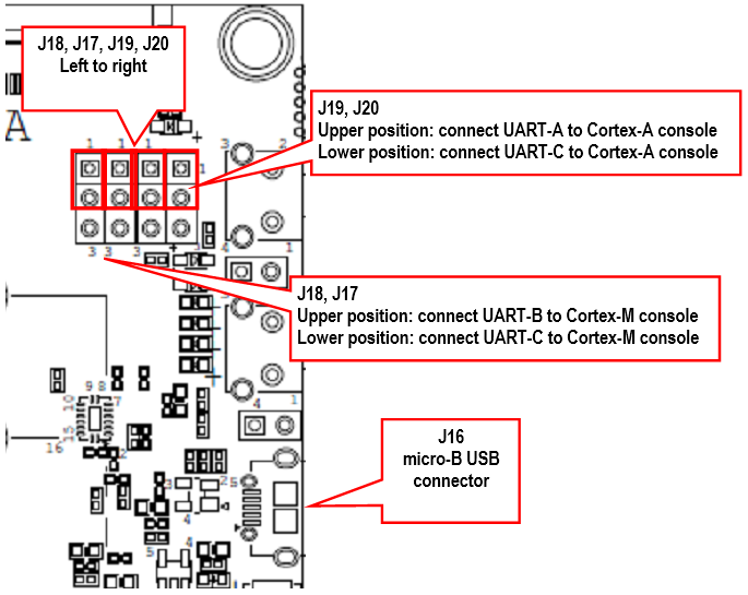
The COM Carrier board version 2 has a dual channel UART-to-USB bridge, meaning that you will get two UART interfaces via one USB cable connected between the micro-B USB connector (J16) on the carrier board and your PC.
There are jumpers on the carrier board that lets you select which UART interface that is connected to the UART-to-USB bridge, see the figure below. Jumpers J19/J20 let you select between using UART-A or UART-C as console for the Cortex-A side. By default, these jumpers select the UART-A interface, that is, jumpers are in upper position. This is the position they should have for the iMX8M (u)COM boards.
Jumpers J17/18 lets you select between using UART-B or UART-C as console for the Cortex-M side. By default, these jumpers are not inserted, but they should be in upper position for the iMX8M Quad COM board and in the lower position for the iMX8M Mini uCOM and iMX8M Nano uCOM boards.
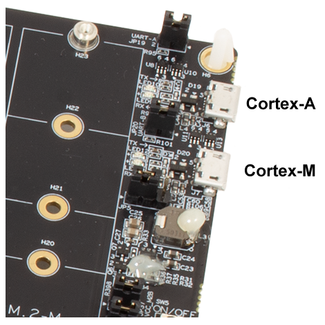
The SOM Carrier board has two micro USB connectors for the UART interfaces. They are located in the top right corner of the carrier board. The top connector is for the Cortex-A core and the bottom for the Cortex-M core.
Terminal application
You need a terminal application (two instances of it to connect both to the Cortex-A side and the Cortex-M side). We recommend Tera Term, but you can use the terminal application of your choice. Connect to the virtual COM ports using 115200 as baud rate, 8 data bits, 1 stop bit, and no parity.
Download and start an application
This section describes how to download and start a pre-compiled application.
Update boot partition with needed files
The remaining parts of this chapter assumes that the first partition of the eMMC contains the pre-compiled applications.
If you have programmed your board using a UUU bundle from 2020-11-04 or later the files will already have been copied to the eMMC flash. If you have programmed using an older version and don’t want to update you can follow these instructions.
It is not necessary to have the Cortex-M applications on the eMMC, but for simplicity the following instructions in this section assumes they are.
Download pre-compiled applications
Go to https://sw.embeddedartists.com and download the file compiled_cortex_m_apps.zip for your (u)COM board.
Copy via USB memory stick
There are several ways to copy these pre-compiled files to the eMMC, but here we will use a USB memory stick.
-
Unpack the file
compiled_cortex_m_apps.zipfile and copy the unpacked files to the USB memory stick. This is something you do on your computer. -
Boot into Linux and insert the USB memory stick into the USB host port on the carrier board. You will see output like below in the console when inserting the USB memory stick. The most important part is the last line that lists the device name (
sda1).[ 23.104504] usb 1-1.2: new high-speed USB device number 4 using ci_hdrc
[ 23.165591] usb 1-1.2: New USB device found, idVendor=0781, idProduct=5406, bcdDevice= 0.10
[ 23.173972] usb 1-1.2: New USB device strings: Mfr=1, Product=2, SerialNumber=3
[ 23.194511] usb 1-1.2: Product: U3 Cruzer Micro
[ 23.199055] usb 1-1.2: Manufacturer: SanDisk Corporation
[ 23.204371] usb 1-1.2: SerialNumber: 0000185A49619848
[ 23.225447] usb-storage 1-1.2:1.0: USB Mass Storage device detected
[ 23.264533] scsi host0: usb-storage 1-1.2:1.0
[ 24.315418] scsi 0:0:0:0: Direct-Access SanDisk U3 Cruzer Micro 2.18 PQ: 0 ANSI: 2
[ 24.334542] scsi 0:0:0:1: CD-ROM SanDisk U3 Cruzer Micro 2.18 PQ: 0 ANSI: 2
[ 24.345768] sd 0:0:0:0: [sda] 8015505 512-byte logical blocks: (4.10 GB/3.82 GiB)
[ 24.364543] sd 0:0:0:0: [sda] Write Protect is off
[ 24.373248] sd 0:0:0:0: [sda] No Caching mode page found
[ 24.378630] sd 0:0:0:0: [sda] Assuming drive cache: write through
[ 24.443649] sda: sda1 -
Mount the USB memory stick and eMMC partition. The USB memory stick has in this example the device name
sda1as can be seen in the output in step 2 above. The partition on the eMMC that we will use is available at/dev/mmcblk2p1, but this can be different for different (u)COM boards.mkdir /mnt/usb
mount /dev/sda1 /mnt/usb
mkdir /mnt/mmcboot
mount /dev/mmcblk2p1 /mnt/mmcboot -
Copy the bin file(s) from the USB memory stick to the boot partition. In this example we are only copying
cm_TCM_hello_world.bin.cp /mnt/usb/cm_TCM_hello_world.bin /mnt/mmcboot/ -
Unmount the devices
umount /mnt/usb
umount /mnt/mmcboot
Change the device tree file
Some of the u-boot environment variables need to be updated.
-
You must have booted into the U-Boot console.
-
Change which device tree file to use by Linux. The example below sets the file to use for the iMX8M Mini uCOM Developer’s Kit V2. If you are using a different board just use the same name as set by default in the
fdt_filevariable and append-m4.setenv fdt_file imx8mmea-ucom-kit_v2-m4.dtb
saveenv
Run from TCM
Make sure you have built an application for TCM or selected a pre-built application for TCM. The application file must have been copied to eMMC as described in the Update boot partition section.
Note: All the U-Boot variables created below (starting with cm_) might already be available as default variables depending on which U-Boot version you are running. You can check if they are available by printing the environment with printenv.
- You must have booted into the U-Boot console.
- Set the file name in the cm_image variable.
setenv cm_image cm_TCM_hello_world.bin - Set the address where the application will run from (TCM memory in this case).
setenv cm_addr 0x7e0000
- Create a variable that loads the application from eMMC
setenv cm_loadimage 'fatload mmc ${mmcdev} ${loadaddr} ${cm_image}'
- Create a variable that will load and boot the application. It loads the image from eMMC to DDR memory, copies from DDR memory to TCM memory and then boots the application. The application is loaded via DDR memory since
fatloadin U-Boot can only load to memory regions that aren’t marked as reserved and the TCM memory is considered reserved.
setenv cm_boot 'run cm_loadimage; cp.b ${loadaddr} ${cm_addr} ${filesize}; dcache flush; bootaux ${cm_addr}'
- Save the changes.
saveenv
- Boot the Cortex-M application.
run cm_boot
Automatically start the Cortex-M application
If you want the Cortex-M application to start during boot of the board follow the instructions below.
- You must have booted into the U-Boot console.
- You should also have followed the instructions in any of the sections above depending on which type of application you use.
- Change the bootcmd variable to first run cm_boot and then boot Linux.
setenv bootcmd "run cm_boot; ${bootcmd}"
saveenv
Remote communication (RPMsg)
Ping-pong application
The RPMsg ping-pong application is an example of communication between the Cortex-A core and the Cortex-M core using the RPMsg API.
- Make sure the
cm_TCM_rpmsg_lite_pingpong_rtos_linux_remote.binfile is available on eMMC as described in the Update boot partition section above. - Follow the instruction in the Run from TCM section for how to run an application from TCM memory, but use the file name
cm_TCM_rpmsg_lite_pingpong_rtos_linux_remote.bin. - Boot the Cortex-M application
run cm_boot - In the console for the Cortex-M you will now see the output below
RPMSG Ping-Pong FreeRTOS RTOS API Demo...
RPMSG Share Base Addr is 0xb8000000 - In the console for Cortex-A boot into Linux
boot - When Linux has booted you need to load the rpmsg pingpong module.
modprobe imx_rpmsg_pingpong - You will now see messages in both consoles / terminals.
TTY application
The RPMsg TTY application is an example of communication between the Cortex-A core and the Cortex-M core using the RPMsg API. A TTY channel will be setup making it possible to send messages from the Cortex-A core to the Cortex-M core from Linux user-space.
- Make sure the
cm_TCM_rpmsg_lite_str_echo_rtos.binfile is available on eMMC as described in the Update boot partition section above. - Follow the instruction in the Run from TCM section for how to run an application from TCM memory, but use the file name
cm_TCM_rpmsg_lite_str_echo_rtos.bin. - Boot the Cortex-M application
run cm_boot - In the console for the Cortex-M you will now see the output below
RPMSG String Echo FreeRTOS RTOS API Demo... - In the console for Cortex-A boot into Linux
boot - When Linux has booted you need to load the rpmsg tty module. You will see a confirmation that a channel has been created (similar as below).
modprobe imx_rpmsg_tty[ 17.860278] imx_rpmsg_tty virtio0.rpmsg-virtual-tty-channel-1.-1.30: new channel: 0x400 -> 0x1e!
[ 17.870207] Install rpmsg tty driver! - From Linux you can now send a message to the Cortex-M side by using the new TTY channel (dev/ttyRPMSG0)
echo hello > /dev/ttyRPMSG30
Software Development Kit (SDK)
NXP provides SDK’s for the iMX8M family of processors. These can be downloaded from NXP’s MCUXpresso website.
Download SDK
Follow these instructions to download an SDK from NXP’s website.
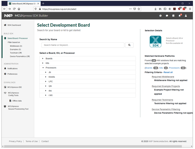
- Go the https://mcuxpresso.nxp.com (you must have an account to create and download an SDK).
- Click on Select Development Board and you will get to the MCUXpresso SDK Builder as shown the first figure below.
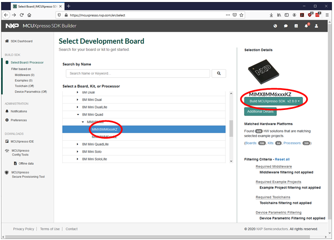
- Choose the i.MX processor you are using. In the second figure below the i.MX 8M Mini is selected.
- Click Build MCUXpresso SDK. This button is shown to the right in second figure below.
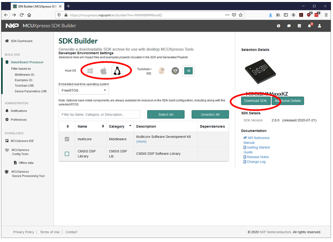
- When the SDK is ready select Host OS (we use Linux in this example) and then click on "Download SDK" as shown in the third figure below.
Setup a Linux host
These instructions are tested on an Ubuntu 18.04 Linux host. You can also run on other Linux hosts or on a Windows host. The SDK contains a "Getting Started" document with more instructions. This document can be found in the docs folder.
- Install toolchain
sudo apt-get install gcc-arm-none-eabi binutils-arm-none-eabi - Install cmake and make
sudo apt-get install cmake make
Build in Linux
Once the toolchain has been installed you can unpack the SDK and build an application.
- Unpack the downloaded SDK (replace
<download dir>with the directory where you downloaded the SDK.cd ~
mkdir 8mm_sdk
cp <download dir>/SDK_2.8.0_MIMX8MM6xxxKZ.tar.gz 8mm_sdk
cd 8mm_sdk
tar -xzvf SDK_2.8.0_MIMX8MM6xxxKZ.tar.gz - The build scripts expect there to be an environment variable called ARMGCC_DIR pointing to the toolchain directory.
export ARMGCC_DIR=/usr - Go the armgcc directory of the application you want to build.
cd boards/evkmimx8mm/rtos_examples/freertos_hello/armgcc - Run the build_debug.sh script to build the debug version of the RAM/TCM target.
./build_debug.sh - Now the application will be available in the debug directory.
ls debugfreertos_hello.bin freertos_hello.elf - You can now copy and run freertos_hello.bin on target as described in chapter 4 above.