iMX 6/7/8/9
Introduction
This document describes how to add wireless functionality with M.2 modules to an iMX Developer’s Kit V2/V3. Linux commands for controlling wireless functionality are also presented.
There are several different iMX Developer’s Kits and there are V2 and V3 versions of some kits, as well. This document refers to all these kits collectively as iMX Developer’s Kits. Please note that all available iMX Developer’s Kits may not support all the presented wireless technologies or more specifically the interface used to communicate with a hardware module. The PCIe interface is for example not supported by all i.MX processors.
The table below lists the processor / M.2 combinations that are supported. A check mark means that combination is supported.
Embedded Artists module – Host processor
| M.2 Module | Wi-Fi Interface | Chipset | Wi-Fi Interface Identifier | iMX93 uCOM iMX8M Nano uCOM iMX6 UL/ULL COM | Modules with PCIe: iMX8M Mini SOM iMX8M Mini uCOM iMX7 Dual uCOM/COM iMX6 SoloX COM |
|---|---|---|---|---|---|
| 1XK M.2 | SDIO | NXP IW416 | mlan0 | ✓ | ✓ |
| 1ZM M.2 | SDIO | NXP 88W8987 | mlan0 | ✓ | ✓ |
| 2DS M.2 | SDIO | NXP 88W8801 | mlan0 | ✓ | ✓ |
| 1YM-SDIO M.2 | SDIO | NXP 88W8997 | mlan0 | ✓ | ✓ |
| 1YM-PCIe M.2 | PCIe | NXP 88W8997 | mlan0 | ✓ | |
| 1XL-SDIO M.2 | SDIO | NXP 88W9098 | mlan0 | ✓ | ✓ |
| 1XL-PCIe M.2 | PCIe | NXP 88W9098 | mlan0 | ✓ | |
| 2EL M.2 | SDIO | NXP IW612 | mlan0 | ✓ | ✓ |
| 2XS-SDIO M.2 | SDIO | NXP 88W9098 | mlan0 | ✓ | ✓ |
| 2XS-PCIe M.2 | PCIe | NXP 88W9098 | mlan0 | ✓ | |
| 2KL-SDIO M.2 | SDIO | NXP IW610F | mlan0 | ✓ | ✓ |
| 2KL-USB M.2 | USB | NXP IW610F | mlan0 | ✓ | ✓ |
| 2LL-SDIO M.2 | SDIO | NXP IW610G | mlan0 | ✓ | ✓ |
| 2LL-USB M.2 | USB | NXP IW610G | mlan0 | ✓ | ✓ |
| 2AE M.2 | SDIO | Infineon CYW4373E | wlan0 | ✓ | ✓ |
| 2AE-USB M.2 | USB | Infineon CYW4373E | wlan0 | ✓ | ✓ |
| 1XA M.2 | PCIe | Infineon CYW54591 | wlan0 | ✓ | |
| 1CX M.2 | PCIe | Infineon CYW4356 | wlan0 | ✓ | |
| 1YN M.2 | SDIO | Infineon CYW43439 | wlan0 | ✓ | ✓ |
| 1LV M.2 | SDIO | Infineon CYW43012 | wlan0 | ✓ | ✓ |
| 1MW M.2 | SDIO | Infineon CYW43455 | wlan0 | ✓ | ✓ |
| 1DX M.2 | SDIO | Infineon CYW4343W | wlan0 | ✓ | ✓ |
| 2EA-SDIO M.2 | SDIO | Infineon CYW55573 | wlan0 | ✓ | ✓ |
| 2EA-PCIe M.2 | PCIe | Infineon CYW55573 | wlan0 | ✓ | |
| 2BZ-SDIO M.2 | SDIO | Infineon CYW54590 | wlan0 | ✓ | ✓ |
| 2BZ-PCIe M.2 | PCIe | Infineon CYW54590 | wlan0 | ✓ | |
| 1WZ M.2 | SDIO | Infineon CYW88359 | wlan0 | ✓ | ✓ |
| 2BC M.2 | SDIO | Infineon CYW4373 | wlan0 | ✓ | ✓ |
| 2BC-USB M.2 | USB | Infineon CYW4373 | wlan0 | ✓ | ✓ |
| 2GF M.2 | SDIO | Infineon CYW43022 | wlan0 | ✓ | ✓ |
| 2FY M.2 | SDIO | Infineon CYW55513 | wlan0 | ✓ | ✓ |
All interfaces, needed tools and kernel configurations described in this document have been added / enabled in the prepared images available at https://sw.embeddedartists.com/. To make changes to your own build, see Yocto.
This table shows the compatibility of the module on different Linux branches supplied by Embedded Artists.
| M.2 Module | ea-6.12.34 | ea-6.12.3 | ea-6.6.23 | ea-6.1.36 | ea-5.15.32 | ea-5.10.72 | ea-5.10.35 | ea-5.4.47 | ea-5.4.24 | ea-4.14.98 | ea-4.14.78 |
|---|---|---|---|---|---|---|---|---|---|---|---|
| 1XK M.2 | ✓ | ✓ | ✓ | ✓ | ✓ | ✓ | ✓ | ||||
| 1ZM M.2 | ✓ | ✓ | ✓ | ✓ | ✓ | ✓ | ✓ | ✓ | ✓ | ||
| 2DS M.2 | ✓ | ✓ | ✓ | ✓ | ✓ | ✓ | ✓ | ||||
| 1YM-SDIO M.2 | ✓ | ✓ | ✓ | ✓ | ✓ | ✓ | ✓ | ✓ | ✓ | ||
| 1YM-PCIe M.2 | ✓ | ✓ | ✓ | ✓ | ✓ | ✓ | ✓ | ✓ | ✓ | ||
| 1XL-SDIO M.2 | ✓ | ✓ | ✓ | ✓ | ✓ | ||||||
| 1XL-PCIe M.2 | ✓ | ✓ | ✓ | ✓ | ✓ | ✓ | ✓ | ||||
| 2EL M.2 | ✓ | ✓ | ✓ | ✓ | |||||||
| 2XS-SDIO M.2 | ✓ | ✓ | ✓ | ✓ | ✓ | ||||||
| 2XS-PCIe M.2 | ✓ | ✓ | ✓ | ✓ | ✓ | ||||||
| 2AE M.2 | ✓ | ✓ | ✓ | ✓ | ✓ | ✓ | ✓ | ||||
| 2AE-USB M.2 | ✓ | ✓ | ✓ | ||||||||
| 2KL M.2 | ✓ | ✓ | ✓ | ||||||||
| 2KL-USB M.2 | ✓ | ✓ | |||||||||
| 2LL M.2 | ✓ | ✓ | ✓ | ||||||||
| 2LL-USB M.2 | ✓ | ✓ | |||||||||
| 1XA M.2 | ✓ | ✓ | ✓ | ✓ | ✓ | ✓ | ✓ | ✓ | ✓ | ||
| 1CX M.2 | ✓ | ✓ | ✓ | ✓ | ✓ | ✓ | ✓ | ✓ | ✓ | ✓ | ✓ |
| 1YN M.2 | ✓ | ✓ | ✓ | ✓ | ✓ | ✓ | ✓ | ||||
| 1LV M.2 | ✓ | ✓ | ✓ | ✓ | ✓ | ✓ | ✓ | ✓ | ✓ | ✓ | ✓ |
| 1MW M.2 | ✓ | ✓ | ✓ | ✓ | ✓ | ✓ | ✓ | ✓ | ✓ | ✓ | ✓ |
| 1DX M.2 | ✓ | ✓ | ✓ | ✓ | ✓ | ✓ | ✓ | ✓ | ✓ | ✓ | ✓ |
| 2EA-SDIO M.2 | ✓ | ✓ | ✓ | ✓ | ✓ | ||||||
| 2EA-PCIe M.2 | ✓ | ✓ | ✓ | ✓ | ✓ | ||||||
| 2BZ-SDIO M.2 | ✓ | ✓ | ✓ | ✓ | ✓ | ||||||
| 2BZ-PCIe M.2 | |||||||||||
| 1WZ M.2 | ✓ | ✓ | ✓ | ✓ | |||||||
| 2BC M.2 | ✓ | ✓ | ✓ | ✓ | ✓ | ||||||
| 2BC-USB M.2 | ✓ | ✓ | ✓ | ||||||||
| 2GF M.2 | ✓ | ✓ | ✓ | ✓ | |||||||
| 2FY M.2 | ✓ | ✓ | ✓ |
Additional documents you might need are:
- The Getting Started document for the iMX Developer's Kit you are using
- (u)COM Board Datasheet for the specific COM board you are using
- (u)COM Carrier Board Datasheet
- M.2 Module Datasheet for the specific M.2 module you are using
This table shows the chipset driver version for each of the Linux branches.
| Linux Branch | Infineon Chipset Driver | NXP Chipset Driver |
|---|---|---|
| ea-6.12.34 | longma | See RN00104_NXP_Wireless_SoC_Features_and_Release_Notes_for_Linux.pdf in NXP Documentation archive |
| ea-6.12.3 | longma | See RN00104_NXP_Wireless_SoC_Features_and_Release_Notes_for_Linux.pdf in NXP Documentation archive |
| ea-6.6.23 | jaculus | See RN00104_NXP_Wireless_SoC_Features_and_Release_Notes_for_Linux.pdf in NXP Documentation archive (Note that it is for 6.6.52 as there is nothing available for 6.6.23) |
| ea-6.1.36 | godzilla | See NXP Wi-Fi Driver Features and Release Notes (Note that it is for 6.1.22 as there is nothing available for 6.1.36) |
| ea-6.1.1 | fafnir | See NXP Wi-Fi Driver Features and Release Notes |
| ea-5.15.32 | indrik | See NXP Wi-Fi Driver Features and Release Notes |
| ea-5.10.72 | cynder | See NXP Wi-Fi Driver Features and Release Notes |
| ea-5.10.35 | cynder | See NXP Wi-Fi Driver Features and Release Notes |
| ea-5.4.47 | zigra | No information available |
| ea-5.4.24 | zigra | No information available |
| ea-4.14.98 | kong | No information available |
| ea-4.14.78 | mothra | No information available |
QuickStart Guide
This is a step-by-step guide to get Wi-Fi and Bluetooth connections up in the shortest possible time. Below are the five simple steps to get up-and-running immediately!
- Follow the "Getting Started" guide for powering the board and getting access to the console.
- Mount the M.2 module.
- Configure the system for the mounted M.2 module.
- Set up the Wi-Fi interface from the Linux console.
- Access and configure the Bluetooth interface.
There are a couple of more sections describing different aspects, like performance measurements with iperf and how to connect specific Bluetooth devices, like a keyboard.
Step #1: Follow "Getting Started" Guide
Before we continue you must identify if you have a V2 or V3 kit. The table below allows you to easily identify the kit version you have.
| iMX Developer's Kit V2 | iMX Developer's Kit V3 |
|---|---|
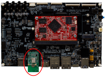 | 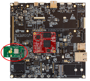 |
| Follow the instructions in the getting started guide to get access to the console and to connect the power supply but keep the board powered off for now. | Follow the instructions in the getting started guide to get access to the console and to connect the power supply but keep the board powered off for now. |
The red circle in the pictures above illustrates where the M.2 module is mounted.
First, power-up your board and verify that you can see the console output when you boot your Linux system. The boot log will look something like below.
U-Boot SPL 2021.04-5.10.35-2.0.0+g450892dd45 (Nov 24 2021 - 09:07:14 +0000)

power_bd71837_init

EA: Using gzipped ddr data from eeprom

DDRINFO: start DRAM init

DDRINFO: DRAM rate 3000MTS

DDRINFO:ddrphy calibration done

DDRINFO: ddrmix config done

Normal Boot

Trying to boot from MMC2

NOTICE:  BL31: v2.4(release):lf-5.10.72-2.2.0-0-g5782363f9

NOTICE:  BL31: Built : 12:17:17, Nov 18 2021


U-Boot 2021.04-5.10.35-2.0.0+g450892dd45 (Nov 24 2021 - 09:07:14 +0000)

CPU:   i.MX8MMQ rev1.0 at 1200 MHz

Reset cause: POR

Model: Embedded Artists i.MX8MM COM Kit

DRAM:  1 GiB

Board: Embedded Artists iMX8M Mini Quad uCOM Ext

00349, A1, WO1121

MMC:   FSL_SDHC: 1, FSL_SDHC: 2

Loading Environment from MMC... OK

... (removed to save space)

Starting kernel ...

[    0.000000] Booting Linux on physical CPU 0x0000000000 [0x410fd034]

[    0.000000] Linux version 5.10.72+g743730fc3894 (oe-user@oe-host) (aarch64-poky-linux-gcc (GCC)

10.2.0, GNU ld (GNU Binutils) 2.36.1.20210209) #1 SMP PREEMPT Wed Feb 9 09:42:10 UTC 2022

[    0.000000] Machine model: Embedded Artists i.MX8MM uCOM Kit

...
Verify that you are running the latest available Linux image available for your board. Check the date you get (marked in red above) and compare it to what is available on https://sw.embeddedartists.com/.
The picture below illustrates an example for the iMX8M Mini Developer’s Kit. If you are not running on the latest release it is recommended to download the image from https://sw.embeddedartists.com/ and follow the instructions in Deploying Images to deploy/download the image.
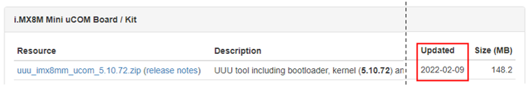
Also note that the dates marked in green above are related to the bootloaders (U-Boot SPL and U-Boot). These dates are not updated every time a new Linux release is made available so make sure it is the date in the red rectangle that is compared.
Step #2: Mount M.2 Module
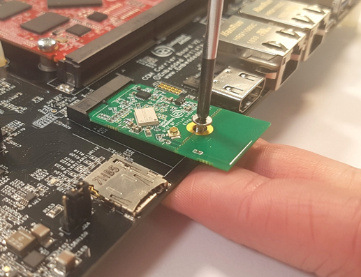
Make sure the iMX Developer's Kit is powered off and then mount the M.2 Module. The picture below illustrates the V2 kit COM Carrier board, and the principles are the same for the V3 kit uCOM Carrier board.

Do not put too much force/pressure on the M2 screw (into the M.2 connector stand-off) so that the PCB is bent. Bending the PCB too much will damage the board!
Use your fingers on the bottom side (while screwing) to give a counter-force, keeping the PCB straight.
Note that if you have a uCOM board with an on-board the Wi-Fi/BT module, then nothing needs to be mounted. The Wi-Fi/BT module is already connected to the host processor. Also note that the M.2 interface on the carrier board is not enabled when there is an on-board Wi-Fi/BT module on the uCOM.

The picture below illustrates the typical angle (about 25 degrees) to use when inserting the M.2 module into the connector. The pictures illustrate another carrier board, but the principle is exactly the same, regardless of carrier board.
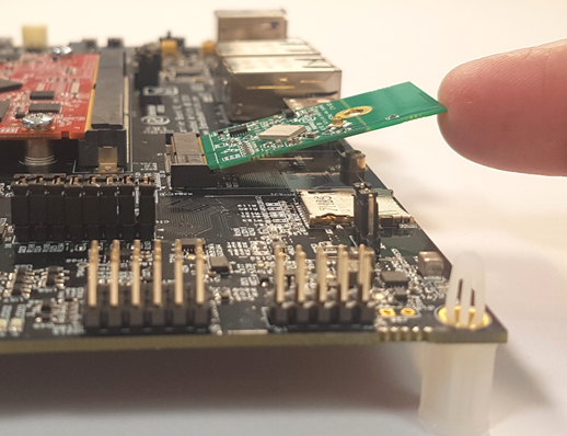
The picture below illustrates how to use two fingers, placed under the grounding stand-off, to avoid bending the board. Make sure to always use this method to avoid damaging the board.
Step #3: Configure the system for the mounted M.2 module
Set the Power on/off switch to On state to power up the board. When the boot process is complete you will be presented with a login prompt. Enter the login credentials below to log in:
   Username: root
   Password: pass
Configuring the platform to use a Wi-Fi M.2 module (or an onboard chip) requires choosing a device tree file to use, selecting libraries to use, setting up configuration files, setting up system services for automatic connection to a network and configuring which geographical region the hardware is being used in so to comply with local regulations. This has been split up into two helper scripts.
switch_module.sh
The first script is switch_module.sh that will select device tree file, configure libraries/utilities and enable the correct systemd service based on which M.2 module will be used.
Run the script without parameters to see the full list of available module names
switch_module.sh
Version: 1.0

Usage:
  /usr/sbin/switch_module.sh  <module>

Where:
  <module> is one of (case insensitive):
     CYW-SDIO, CYW-PCIe, 1CX, 1DX, 1LV, 1MW, 1YN, 2AE, 2AE-USB,
     2BC, 2BC-USB, 1XA, 2BZ, 2EA-SDIO, 2EA-PCIe, 1ZM, 1YM-SDIO,
     1YM-PCIe, 1XK, 2XK, 1XL-SDIO, 1XL-PCIe, 2XS-SDIO, 2XS-PCIe,
     2EL, 2DL, 2DS, CURRENT or OFF
Note that the list above varies depending on CPU and Linux version (see table with Linux versions in Introduction).
CYW-SDIO is an alias for all Infineon/Cypress based modules using SDIO. CYW-PCIE is an alias for all Infineon/Cypress based modules using PCIe. The OFF parameter will disable the systemd service so that it will not automatically start after a reboot, but it will keep the rest of the system configuration.
As an example, to enable the 1ZM M.2 module:
switch_module.sh 1ZM
switch_regions.sh
switch_regions.sh is only available on Linux >= 5.10
The second script, switch_regions.sh, is for regulatory conformance, and it limits the available frequencies to match the requirements in the specified geographical region. This support is only available for a few Wi-Fi chips, at the time of writing they were: 1ZM, 1YM, 1XK and 2DS but the most updated list of supported modules can be found by running the script without any parameters:
switch_regions.sh
Version: 1.0

Usage:
  /usr/sbin/switch_regions.sh  <module> <country code>
Where:
  <module> is one of:
     1zm, 1ym, 1xk, 2ds

  <country code> is one of:
     CA, EU, JP, US
     CA – Canada
     EU - European Union
     JP – Japan
     US - United States
NOTE: Country code for EU will be displayed as DE when you use the command - iw reg get
      For setting the country code EU, user should use: iw reg set DE
If you are using for example a 1ZM module in Europe then set the region with
switch_region.sh 1ZM EU
wpa_supplicant.conf
For the systemd service to work it must know which network to connect to and what the password is. This information is stored in the /etc/wpa_supplicant.conf file. Open it in an editor (e.g. vi or nano) and replace the part marked in red below:
ctrl_interface=/var/run/wpa_supplicant

ctrl_interface_group=0

update_config=1

network={

    key_mgmt=NONE

}
If the SSID is Hello World and the password is MyPassword then change the file to
ctrl_interface=/var/run/wpa_supplicant

ctrl_interface_group=0

update_config=1

network={

    ssid="Hello World"

    psk="MyPassword"

}
If you are using a (u)COM board with onboard Wi-Fi, then follow the instructions in the next section to complete the configuration before rebooting.
If you are using an M.2 Wi-Fi module then your network configuration is completed, and you can reboot to test the new settings. The M.2 module should automatically connect to the desired network.
iMX uCOM Boards with On-Board Solutions
At the time of writing this document, Embedded Artists supplied several iMX uCOM boards with onboard chips. These boards require extra configuration to use as they use different device tree files.
For Linux >= 5.10:
| iMX (u)COM Board | iMX Developer’s Kit V3 | iMX Developer’s Kit V2 |
|---|---|---|
| iMX7 ULP uCOM with onboard 1LV | Not supported | imx7ulpea-ucom-kit_v2-1lv.dtb |
| iMX8M Mini uCOM with onboard 1MW | imx8mm-ea-ucom-kit_v3-1mw.dtb | imx8mm-ea-ucom-kit_v2-1mw.dtb |
| iMX8M Mini uCOM with onboard 1ZM | As of February 2022, not supported | As of February 2022, not supported |
| iMX8M Nano uCOM with onboard 1MW | imx8mn-ea-ucom-kit_v3-1mw.dtb | imx8mn-ea-ucom-kit_v2-1mw.dtb |
| iMX8M Nano uCOM with onboard 1ZM | As of February 2022, not supported | As of February 2022, not supported |
For Linux before 5.10:
| iMX (u)COM Board | iMX Developer’s Kit V3 | iMX Developer’s Kit V2 |
|---|---|---|
| iMX7 ULP uCOM with onboard 1LV | Not supported | imx7ulpea-ucom-kit_v2-1lv.dtb |
| iMX8M Mini uCOM with onboard 1MW | Not supported | imx8mm-ea-ucom-kit_v2-1mw.dtb |
| iMX8M Nano uCOM with onboard 1MW | Not supported | imx8mn-ea-ucom-kit_v2-1mw.dtb |
Pick the name of the device tree file from the table above and then select your module with:
switch_module.sh <module name>
fw_setenv fdt_file <dtb file>
As an example, for an iMX8M Nano uCOM with onboard 1MW on an iMX Developer’s Kit V3
switch_module.sh 1MW
fw_setenv fdt_file imx8mn-ea-ucom-kit_v3-1mw.dtb
Step #4: Linux Console – Search for available networks
When the boot process is complete you will be presented with a login prompt. Enter the login credentials below to log in:
   Username: root
   Password: pass
The Wi-Fi modules use different device names – either mlan0 or wlan0. Use the table in Introduction to find out what your module is using. The examples below all use mlan0 as device name – just replace it with wlan0 if that is what your module is using.
Run a scan of networks in range:
iw dev mlan0 scan
or
iwlist mlan0 scan
Both commands are very verbose, so it is probably a good idea to limit the result like this:
iw dev mlan0 scan | grep SSID
        SSID: EA Guest
        SSID: VSG1
        SSID: COMHEM_73ee11
        SSID: DIRECT-4C-HP ENVY Photo 6200
        ...
Test the network connection with ping (stop with Ctrl+C):
ping www.sunet.se
PING www.sunet.se (192.36.171.231): 56 data bytes
64 bytes from 192.36.171.231: seq=0 ttl=56 time=16.412 ms
64 bytes from 192.36.171.231: seq=1 ttl=56 time=18.279 ms
64 bytes from 192.36.171.231: seq=2 ttl=56 time=19.125 ms
...
If your router is not connected to Internet, then ping the IP number of the router instead. The IP number can be found like this:
ip route
default via 192.168.0.1 dev mlan0 metric 10
192.168.0.0/24 dev mlan0 proto kernel scope link src 192.168.0.4
ping 192.168.0.1
PING 192.168.0.1 (192.168.0.1): 56 data bytes
64 bytes from 192.168.0.1: seq=0 ttl=56 time=16.412 ms
64 bytes from 192.168.0.1: seq=1 ttl=56 time=18.279 ms
64 bytes from 192.168.0.1: seq=2 ttl=56 time=19.125 ms
...
There are several ways to see the status of your connection and the network it is connection to. Here is one example (not showing the output):
iw dev mlan0 link
To see the region setting (if supported by your module) use this command:
iw reg get
global
country DE: DFS-ETSI
        (2400 - 2483 @ 40), (N/A, 20), (N/A)
        (5150 - 5250 @ 80), (N/A, 23), (N/A), NO-OUTDOOR, AUTO-BW
        (5250 - 5350 @ 80), (N/A, 20), (0 ms), NO-OUTDOOR, DFS, AUTO-BW
        (5470 - 5725 @ 160), (N/A, 26), (0 ms), DFS
        (5725 - 5875 @ 80), (N/A, 13), (N/A)
        (57000 - 66000 @ 2160), (N/A, 40), (N/A)
The output shows that the EU region (displayed as country DE) is selected.
Optional Manual Network Control
If you want to manually start the network instead of using the systemd service that switch_module.sh sets up, then disable the service with this command and then reboot
switch_module.sh off
reboot
After rebooting, configure the network name and password in /etc/wpa_supplicant.conf and then connect to it with
wpa_supplicant -B -i mlan0 -D nl80211 -c /etc/wpa_supplicant.conf
If that command completes successfully, you should be connected to the network. Check that you got an IP number (192.168.1.5 in the example below):
ifconfig mlan0
mlan0     Link encap:Ethernet  HWaddr 2C:4C:C6:F4:D3:D0
          inet addr:192.168.1.5  Bcast:192.168.1.255  Mask:255.255.255.0
          inet6 addr: fe80::2e4c:c6ff:fef4:d3d0/64 Scope:Link
          UP BROADCAST RUNNING MULTICAST  MTU:1500  Metric:1
          RX packets:17 errors:0 dropped:0 overruns:0 frame:0
          TX packets:62 errors:0 dropped:0 overruns:0 carrier:0
          collisions:0 txqueuelen:1000
          RX bytes:2319 (2.2 KiB)  TX bytes:7447 (7.2 KiB)
If you don’t get an IP number, then run the following command to request one
udhcpc -i mlan0
The network should now work until you reboot or power down the hardware.
Step #5: Access and Configure Bluetooth Devices
All the Bluetooth devices use the UART interface. The device name for that interface is different depending on the (u)COM Board. You do not need to keep track of this device name since the bluetooth_up.sh script handles this automatically.
You must follow the instructions in Step #3 and select the correct M.2 module before trying anything in this section.
To bring up the Bluetooth interfaces run this command:
/opt/ea/bluetooth_up.sh
Setting TTY to N_HCI line discipline
Device setup complete
< HCI Command: ogf 0x3f, ocf 0x0009, plen 4
  C0 C6 2D 00
> HCI Event: 0x0e plen 4
  01 56 0C 00
[ 3065.661301] Bluetooth: hci0: sending frame failed (-49)
Setting TTY to N_HCI line discipline
Device setup complete
Scanning ...
To run a scan again, use hcitool scan
The output from the command is different and depends on which module is being used. Note that there are a couple of error messages that can appear for the modules with NXP chipsets that can be safely ignored (the second one is found in the output above):
Can't init device hci0: Invalid argument (22)Bluetooth: hci0: sending frame failed (-49)Bluetooth: hci0: command 0x1001 tx timeout
The module should now be up and running and to scan for other Bluetooth devices in range:
hcitool scan
Scanning ...
        94:87:0B:35:F2:19       Samsung Galaxy S7
Use the interactive bluetoothctl command line tool to search for devices, pair with a device (the Galaxy Nexus phone), connect to it and then find some information about it:
bluetoothctl
[bluetooth] power on
[bluetooth] agent on
[bluetooth] scan on
Discovery started
[CHG] Controller D8:FC:93:E4:1E:A6 Discovering: yes
[NEW] Device B0:D0:00:38:00:C6 Galaxy Nexus
[NEW] Device 40:2B:A1:5F:7F:46 MW600
[bluetooth] pair B0:D0:00:38:00:C6
Attempting to pair with B0:D0:00:38:00:C6
[CHG] Device B0:D0:00:38:00:C6 Connected: yes
[CHG] Device B0:D0:00:38:00:C6 Modalias: bluetooth:v000Fp1200d1436
[CHG] Device B0:D0:00:38:00:C6 UUIDs:
        00001105-0000-1000-8000-00805f9b34fb
        0000110a-0000-1000-8000-00805f9b34fb
        0000110c-0000-1000-8000-00805f9b34fb
        00001112-0000-1000-8000-00805f9b34fb
        00001115-0000-1000-8000-00805f9b34fb
        00001116-0000-1000-8000-00805f9b34fb
        0000111f-0000-1000-8000-00805f9b34fb
        0000112f-0000-1000-8000-00805f9b34fb
        00001200-0000-1000-8000-00805f9b34fb
[CHG] Device B0:D0:00:38:00:C6 Paired: yes
Pairing successful
[bluetooth] scan off
[bluetooth] devices
Device B0:D0:00:38:00:C6 Galaxy Nexus
[bluetooth] connect B0:D0:9C:38:84:C6
Attempting to connect to B0:D0:9C:38:84:C6
[CHG] Device B0:D0:9C:38:84:C6 Connected: yes
Connection successful
[bluetooth] info B0:D0:00:38:00:C6
Device B0:D0:00:38:00:C6
     Name: Galaxy Nexus
     Alias: Galaxy Nexus
     Class: 0x5a020c
     Icon: phone
     Paired: yes
     Trusted: yes
     Blocked: no
     Connected: yes
     LegacyPairing: no
     UUID: OBEX Object Push          (00001105-0000-1000-8000-00805f9b34fb)
     UUID: Audio Source              (0000110a-0000-1000-8000-00805f9b34fb)
     UUID: A/V Remote Control Target (0000110c-0000-1000-8000-00805f9b34fb)
     UUID: Headset AG                (00001112-0000-1000-8000-00805f9b34fb)
     UUID: PANU                      (00001115-0000-1000-8000-00805f9b34fb)
     UUID: NAP                       (00001116-0000-1000-8000-00805f9b34fb)
     UUID: Handsfree Audio Gateway   (0000111f-0000-1000-8000-00805f9b34fb)
     UUID: Phonebook Access Server   (0000112f-0000-1000-8000-00805f9b34fb)
     UUID: PnP Information           (00001200-0000-1000-8000-00805f9b34fb)
     Modalias: bluetooth:v000Fp1200d1436
[bluetooth] quit
Using the sdptool command it is possible to find even more information (only showing first part here):
sdptool browse B0:D0:00:38:00:C6
Browsing B0:D0:00:38:00:C6 ...
Service Name: Headset Gateway
Service RecHandle: 0x10000
Service Class ID List:
  "Headset Audio Gateway" (0x1112)
  "Generic Audio" (0x1203)
Protocol Descriptor List:
  "L2CAP" (0x0100)
  "RFCOMM" (0x0003)
    Channel: 2
Profile Descriptor List:
  "Headset" (0x1108)
    Version: 0x0102
Additional Links
- https://wiki.archlinux.org/index.php/Bluetooth_headset
- https://wiki.archlinux.org/index.php/Bluetooth
What's Next
To learn more about using Wi-Fi and Bluetooth in Linux, see the How-To Guides.
To learn about how to integrate M.2 modules in your own project, see M.2 Integration Guide.
To learn how to build your own software, see Yocto.
Guides and information about different application development options can be found under Application Processors.