iMX RT and NXP/Marvell
Introduction
This section is a step-by-step guide to get Wi-Fi up and running in the shortest possible time:
- The first step is to download and install the SDK.
- The second step describes how to physically mount the M.2 module.
- The third step describes how to set up, modify, and run the example project.
Above are the three simple steps to get up-and-running immediately!
NXP's SDK supports several IDEs, but this guide is focusing on the free MCUXpresso IDE from NXP. Combining this document and the more general Program Development Guide should make it easy to use another IDE as well.
note
This document focuses only on the NXP/Marvell based modules as the support for Cypress/Infineon was removed in SDK 2.10.0. For information about Cypress/Infineon modules see here. In SDK 2.15.000, the support for the ABR module was dropped.
- Older versions
- SDK 2.15.000
| NXP IW416 | NXP 88W8801 | NXP 88W8987 | NXP MW32x | |
|---|---|---|---|---|
| 1XK | 2DS | 1ZM | ABR | |
| SDIO | SDIO | SDIO | UART | |
| Board | ||||
| imxrt1052 | -- | -- | -- | -- |
| imxrt1062 | Wi-Fi/BT | Wi-Fi | Wi-Fi/BT | -- |
| imxrt1064 1 | Wi-Fi | Wi-Fi | Wi-Fi | Wi-Fi |
| imxrt1166 | Wi-Fi | Wi-Fi | Wi-Fi | Wi-Fi |
| imxrt1176 | Wi-Fi/BT | Wi-Fi | Wi-Fi/BT | Wi-Fi |
| NXP IW416 | NXP IW612 | NXP 88W8801 | NXP 88W8987 | NXP MW32x | |
|---|---|---|---|---|---|
| 1XK | 2EL | 2DS | 1ZM | ABR 2 | |
| SDIO | SDIO | SDIO | SDIO | UART | |
| Board | |||||
| imxrt1052 | -- | -- | -- | -- | -- |
| imxrt1062 | Wi-Fi/BT | Wi-Fi/BT | Wi-Fi | Wi-Fi/BT | -- |
| imxrt1064 1 | Wi-Fi | -- | Wi-Fi | Wi-Fi | -- |
| imxrt1166 | Wi-Fi | Wi-Fi | Wi-Fi | Wi-Fi | -- |
| imxrt1176 | Wi-Fi/BT | Wi-Fi/BT | Wi-Fi | Wi-Fi/BT | -- |
2 Support removed in SDK 2.15.000
Further Information
- Bluetooth Specifications
- Bluetooth Profiles
- Documents included in the
docs/folder of the NXP SDK:- Getting Started with MCUXpresso SDK for MIMXRT1170-EVK.pdf
- MCUXpresso SDK API Reference Manual_MIMXRT1176.pdf
- UM11441-Getting-Started-with-NXP-based-Wireless-Modules-and-i.MX-RT-Platform-Running-on-RTOS.pdf
- UM11442-NXP-Wi-Fi-and-Bluetooth-Demo-Applications-for-i.MX-RT-platforms-User-Guide.pdf
- Getting Started with NXP Wi-Fi Modules Using i.MX RT Platform
Step #1: Downloading and Installing MCUXpresso SDK
This section will walk you through the installation of the MCUXpresso SDK, which is a package of sample software projects (with device drivers and peripheral examples and demos) that will get you started immediately with your i.MX RT software development. Note that even though the name of the SDK suggests the code package is for the MCUXpresso IDE, the sample projects have project files for other IDEs as well, such as Keil uVision/MDK, IAR Embedded Workbench, and more.
Start by downloading the patched SDK (making sure to pick the correct version according to the table above) from this URL: http://imx.embeddedartists.com/.
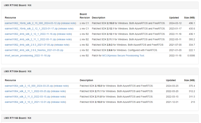
Save the file on your computer. Note the download location. The file name always contains the CPU, SDK version and release date.
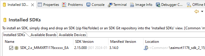
The SDK needs to be installed in MCUXpresso before it can be used. To do that start MCUXpresso and then drag-n-drop the downloaded SDK archive (eaimxrt1176_sdk_2_15_000_2024-02-20.zip) on to the "Installed SDKs" tab:
Step #2: Mount M.2 Module
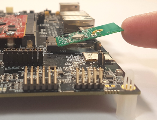
Make sure the iMX RT Developer's Kit is powered off and then mount the M.2 Module, as illustrated in the pictures below:


note
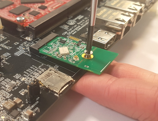
Do not put too much force/pressure on the M2 screw (into the M.2 connector stand-off) so that the PCB is bent. Bending the PCB too much will damage the board!
Use your fingers on the bottom side (while screwing) to give a counter-force, keeping the PCB straight.
The picture below illustrates the typical angle (about 25 degrees) to use when inserting the M.2 module into the connector. The pictures illustrate another carrier board, but the principle is exactly the same, regardless of carrier board.
The picture below illustrates how to use two fingers, placed under the grounding stand-off, to avoid bending the board. Make sure to always use this method to avoid damaging the board.
Step #3: Import, Configure, Run Example
Running any of the examples requires the following steps:
- Import the example
- Select which Wi-Fi solution to use
- Configure the example for your environment (e.g. SSID + password for your network)
- Compile and debug/run
Import Example
The following steps will guide you through opening the wifi_cli application from the SDK.
- Install the SDK as described in Step #1 if you have not done so already
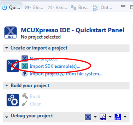
- Click the Import SDK example(s)... link in the Quickstart Panel.
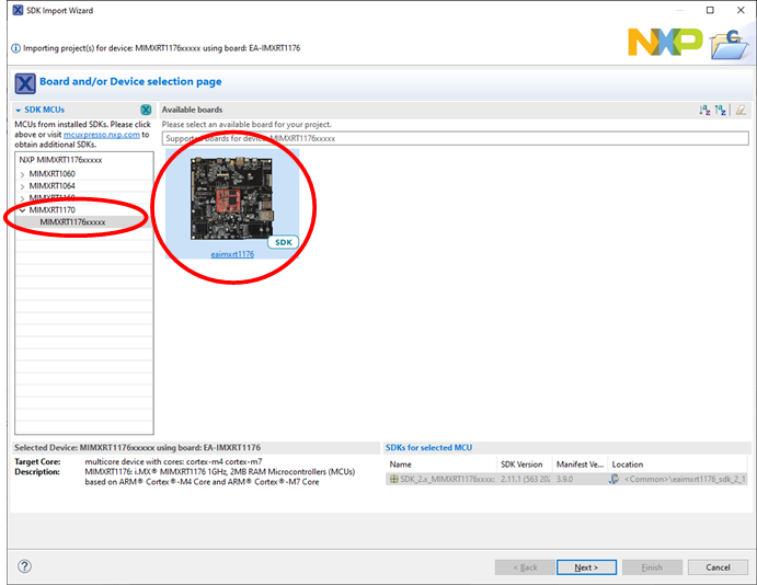
- This step will use the iMX RT1176, but the instructions are the same for any of the supported iMX RT boards. Select the MIMXRT1170 and eaimxrt1176. Click Next to go to the project selector.
- Select the
wifi_cliexample and make sure to switch from Semihost to UART for the SDK Debug Console.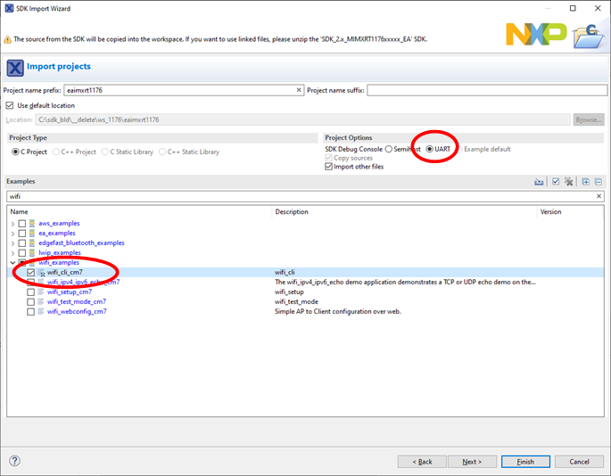
- With the changes made, click Finish to have MCUXpresso complete the project setup
Select M.2 Module
The first thing to do after importing a new project it to make sure that it is setup for the correct M.2 module. This is done with a define in app_config.h for Wi-Fi projects or app_bluetooth_config.h for Bluetooth projects. The line is surrounded with TEST_ANCHOR comments and looks like this:
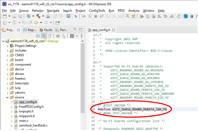
Select what to define based on what you use. Note that not all combinations are available in every example and for every board (e.g. the 2DS module cannot be selected for a Bluetooth example as it does not support Bluetooth).
| Define | Comment |
|---|---|
WIFI_88W8801_BOARD_MURATA_2DS_M2 | 2DS M.2 module |
WIFI_IW416_BOARD_MURATA_1XK_M2 | 1XK M.2 module |
WIFI_IW416_BOARD_MURATA_1XK_ONBOARD | Special mounting option for some OEM/uCOM boards to have an onboard 1XK chip |
WIFI_88W8987_BOARD_MURATA_1ZM_M2 | 1ZM M.2 module |
WIFI_88W8801_BOARD_MURATA_2DS_USD | 2DS M.2 module in uSD-to-M.2 adapter in uSD socket |
WIFI_IW416_BOARD_MURATA_1XK_USD | 1XK M.2 module in uSD-to-M.2 adapter in uSD socket |
WIFI_88W8987_BOARD_MURATA_1ZM_USD | 1ZM M.2 module in uSD-to-M.2 adapter in uSD socket |
WIFI_IW612_BOARD_MURATA_2EL_M2 | 2EL M.2 module |
Configure The Example
Some Wi-Fi examples (like the wifi_cli example) don’t need any configuration as everything is handled at runtime (searching, adding networks, connecting etc.)
However, most of the Wi-Fi examples have settings that must be configured before compiling for the program to connect to your network or to use the correct channel etc.
The settings are typically found in the project’s main file, like this for the wifi_setup example:
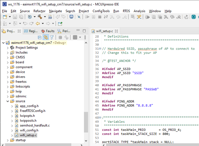
These are some common configuration options:
| Define | Comment |
|---|---|
AP_SSID | SSID of the Access Point that the example will create |
AP_PASSPHRASE | Password for the Access Point |
PING_ADDR | Address that the example will attempt to ping |
WIFI_SSID | SSID of the network to connect to |
WIFI_PASSWORD | Password |
Compile and Run/Debug
To download and run the application, perform these steps:
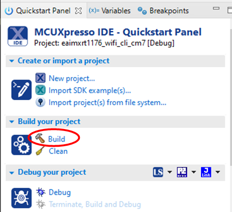
- Click Build in the Quickstart Panel
- The program builds without errors
- Connect a debug probe (LPC-Link2, ULINK2, J-LINK, MCU-Link etc.) to the iMX RT Developer’s Kit and to your PC. See chapter Debug Interface for details how to connect the debug probe
- Open the terminal application on the PC, such as TeraTerm or PuTTY, and connect to the debug serial port number. Configure the terminal with 115200 baud, 8N1. You can alter the baud rate be searching for the reference BOARD_DEBUG_UART_BAUDRATE variable in file:
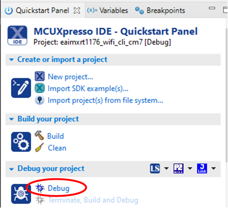
board.h - Click the "Debug" button in the Quickstart Panel to download the application to the target.
- The application is then downloaded to the target and automatically runs to the main() function.
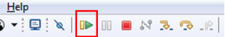
- Run the code by clicking the "Resume" button to start the application.
Explanation of one example – wifi_cli
This will describe how to use the wifi_cli example.
The wifi_cli example presents a shell in the terminal in which you can enter commands. At the start it shows all the available commands (same as running the help command):
help
wlan-reset
wlan-version
wlan-mac
wlan-thread-info
wlan-net-stats
wlan-set-mac <MAC_Address>
wlan-scan
wlan-scan-opt ssid <ssid> bssid ...
wlan-add <profile_name> ssid <ssid> bssid...
wlan-remove <profile_name>
wlan-list
wlan-connect <profile_name>
wlan-connect-opt <profile_name> ...
wlan-reassociate
wlan-start-network <profile_name>
wlan-stop-network
wlan-disconnect
wlan-stat
wlan-info
wlan-address
wlan-get-uap-channel
wlan-get-uap-sta-list
wlan-ieee-ps <0/1>
wlan-set-ps-cfg <null_pkt_interval>
wlan-deep-sleep-ps <0/1>
wlan-get-beacon-interval
wlan-set-max-clients-count <max clients count>
wlan-rts <sta/uap> <rts threshold>
wlan-frag <sta/uap> <fragment threshold>
wlan-host-11k-enable <0/1>
wlan-host-11k-neighbor-req [ssid <ssid>]
wlan-host-11v-bss-trans-query <0..16>
wlan-sta-filter  <filter mode> [<mac address list>]
wlan-roaming <0/1> <rssi_threshold>
wlan-multi-mef <ping/arp/multicast/del> [<action>]
wlan-send-hostcmd
wlan-set-uap-bandwidth <1/2> 1:20 MHz 2:40MHz
wlan-set-uap-hidden-ssid <0/1/2>
wlan-eu-crypto-rc4 <EncDec>
wlan-eu-crypto-aes-wrap <EncDec>
wlan-eu-crypto-aes-ecb <EncDec>
wlan-eu-crypto-ccmp-128 <EncDec>
wlan-eu-crypto-ccmp-256 <EncDec>
wlan-eu-crypto-gcmp-128 <EncDec>
wlan-eu-crypto-gcmp-256 <EncDec>
wlan-ft-roam <bssid> <channel>
wlan-set-antcfg <ant mode> [evaluate_time]
wlan-get-antcfg
wlan-scan-channel-gap <channel_gap_value>
wlan-set-regioncode <region-code>
wlan-get-regioncode
wlan-11d-enable <sta/uap> <0/1>
wlan-tx-ampdu-prot-mode <mode>
wlan-rssi-low-threshold <threshold_value>
wlan-get-signal
wlan-set-su <0/1>
wlan-set-forceRTS <0/1>
wlan-get-turbo-mode <STA/UAP>
wlan-set-turbo-mode <STA/UAP> <mode>
wlan-set-multiple-dtim <value>
wlan-cloud-keep-alive <start/stop/reset>
wlan_tcp_client dst_ip <dst_ip> src_port <src_port> dst_port <dst_port>
wlan-set-country <country_code_str>
wlan-set-country-ie-ignore <0/1>
wlan-auto-reconnect <0/1/2> [<reconnect counter> <reconnect interval> <flags>]
wlan-get-txpwrlimit <subband>
wlan-set-txpwrlimit
wlan-set-chanlist-and-txpwrlimit
wlan-set-chanlist
wlan-get-chanlist
wlan-set-txratecfg <sta/uap> <format> <index>
wlan-get-txratecfg <sta/uap>
wlan-get-data-rate <sta/uap>
wlan-get-pmfcfg
wlan-uap-get-pmfcfg
wlan-set-ed-mac-mode <interface> <ed_ctrl_2g> <ed_offset_2g> <ed_ctrl_5g> <ed_offset_5g>
wlan-get-ed-mac-mode <interface>
ping [-s <packet_size>] [-c <packet_count>] [-W <timeout in sec>] <ipv4/ipv6 address>
iperf [-s|-c <host>|-a|-h] [options]
dhcp-stat
It is possible to get more information about a command by typing the command followed by help:
wlan-add help
Usage:
For Station interface
  For DHCP IP Address assignment:
    wlan-add <profile_name> ssid <ssid> [wpa2 <psk/psk-sha256/ft-psk> <secret>] [mfpc <1> mfpr <0>]
      If using WPA2 security, set the PMF configuration as mentioned above.
    wlan-add <profile_name> ssid <ssid> <owe_only> mfpc 1 mfpr 1
      If using OWE only security, always set the PMF configuration.
    wlan-add <profile_name> ssid <ssid> [wpa3 sae <secret> [pwe <0/1/2>] mfpc <1> mfpr <0/1>]
      If using WPA3 SAE security, always set the PMF configuration.
    wlan-add <profile_name> ssid <ssid> [wpa2 psk psk-sha256 <secret> wpa3 sae <secret>] [mfpc <1> mfpr <0>]
      If using WPA2/WPA3 Mixed security, set the PMF configuration as mentioned above.
  For static IP address assignment:
    wlan-add <profile_name> ssid <ssid>
    ip:<ip_addr>,<gateway_ip>,<netmask>
    [bssid <bssid>] [channel <channel number>]
    [wpa2 <psk/psk-sha256/ft-psk> <secret>] [owe_only] [wpa3 sae <secret>] [mfpc <0/1> mfpr <0/1>]
For Micro-AP interface
    wlan-add <profile_name> ssid <ssid>
    ip:<ip_addr>,<gateway_ip>,<netmask>
    role uap [bssid <bssid>]
    [channel <channelnumber>]
    [wpa2 <psk/psk-sha256> <secret>] [wpa3 sae <secret> [pwe <0/1/2>] [tr <0/1>]]
    [owe_only ]
    [mfpc <0/1>] [mfpr <0/1>]

    [capa <11n/legacy>]
If Set channel to 0, set acs_band to 0 1.
0: 2.4GHz channel   1: 5GHz channel  Not support to select dual band automatically.
Error: invalid number of arguments
To scan for Wi-Fi networks, run the wlan-scan command:
wlan-scan
Scan scheduled...

# 10 networks found:
60:38:E0:9D:B6:F7  "VSG1_5G" Infra
        mode: 802.11N
        channel: 100
        rssi: -50 dBm
        security: WPA2
        WMM: YES
        802.11V: YES
        802.11W: NA
60:38:E0:9D:B6:F8  "VSG1" Infra
        mode: 802.11N
        channel: 13
        rssi: -61 dBm
        security: WPA2
        WMM: YES
        802.11V: YES
        802.11W: NA
12:5A:5B:AA:5E:6E  "CityTest" Infra
        mode: 802.11N
        channel: 1
        rssi: -79 dBm
        security: WPA2
        WMM: YES
        802.11K: YES
        802.11V: YES
        802.11W: NA
...
It will show the networks and if/how they are protected.
Before you can connect to a network it must be configured which is done with the wlan-add command. Assuming you want to connect to the VSG1 network with password test1234 and give it the alias "hello":
wlan-add hello ssid VSG1_5G wpa2 psk test1234
Added "hello"
wlan-list
1 network:
"hello"
        SSID: VSG1_5G
        BSSID: 00:00:00:00:00:00
        channel: (Auto)
        role: Infra
        security: WPA2

        IPv6 Addresses
Now that there is a network, connect to it.
wlan-connect hello
Connecting to network...
Use 'wlan-stat' for current connection status.

# ========================================
app_cb: WLAN: received event 1
========================================
app_cb: WLAN: authenticated to network
========================================
app_cb: WLAN: received event 0
========================================
app_cb: WLAN: connected to network
Connected to following BSS:
SSID = [VSG1_5G]
IPv4 Address: [10.158.186.137]
IPv6 Address: Link-Local : FE80::2E4C:C6FF:FEF4:D3D0 (Preferred)
To show some information about the network that you are connected to, use wlan-stat, wlan-info or wlan-address:
wlan-stat
Station connected (Active)
uAP stopped
wlan-info
Station connected to:
"hello"
        SSID: VSG1_5G
        BSSID: 60:38:E0:9D:B6:F7
        channel: 100
        role: Infra
        security: WPA2

        IPv4 Address
        address: DHCP
                IP:             10.158.186.137
                gateway:        10.158.186.69
                netmask:        255.255.255.0
                dns1:           10.158.186.69
                dns2:           0.0.0.0

        IPv6 Addresses
        Link-Local   :  FE80::2E4C:C6FF:FEF4:D3D0 (Preferred)

uAP not started
wlan-address
        IPv4 Address
        address: DHCP
                IP:             10.158.186.137
                gateway:        10.158.186.69
                netmask:        255.255.255.0
                dns1:           10.158.186.69
                dns2:           0.0.0.0

        IPv6 Addresses
        Link-Local   :  FE80::2E4C:C6FF:FEF4:D3D0 (Preferred)
To test that it really is connected to a network, try using ping.
ping help
Incorrect usage
Usage:
        ping [-s <packet_size>] [-c <packet_count>] [-W <timeout in sec>] <ip_address>
Default values:
        packet_size: 56
        packet_count: 10
        timeout: 2 sec
ping -c 2 8.8.8.8
PING 8.8.8.8 (8.8.8.8) 56(84) bytes of data
64 bytes from 8.8.8.8: icmp_req=1 ttl=113 time=94 ms
64 bytes from 8.8.8.8: icmp_req=2 ttl=113 time=211 ms

--- 10.158.186.137 ping statistics ---
2 packets transmitted, 2 received, 0% packet loss
Ping is a great way to test if the hardware is connected to the network, or not, but to really test the network interface it is better to use a program like iperf. Iperf requires both a server and a client to run the tests. The wifi_cli program can act as client with the server software either installed on a computer on the local network (https://iperf.fr/iperf-download.php or https://sourceforge.net/projects/iperf2/) or one of the online servers can be used (https://iperf.fr/iperf-servers.php). It is also possible to run wifi_cli in server mode and the client on a PC in the same local network.
note
Make sure to select the latest version of the 2.* branch (2.2.0 seems to be the last released version) when downloading the iperf software from https://iperf.fr/iperf-download.php or https://sourceforge.net/projects/iperf2/. Version >=3.0 is not supported by this example, and it will not work as iperf and iperf3 are completely different protocols.
The iperf command in wifi_cli has several options:
iperf help
Incorrect usage
Usage:
        iperf [-s|-c <host>|-a] [options]
        iperf [-h]

        Client/Server:
           -u             use UDP rather than TCP
           -B    <host>   bind to <host> (including multicast address)
           -V             Set the domain to IPv6 (send packets over IPv6)
           -a             abort ongoing iperf session
           -p             server port to listen on/connect to
        Server specific:
           -s             run in server mode. Support 8 parallel traffic(-P) maximum from client side
           -D             Do a bidirectional UDP test simultaneously and with -d from external iperf client
        Client specific:
           -c    <host>   run in client mode, connecting to <host>
           -d             Do a bidirectional test simultaneously
           -r             Do a bidirectional test individually
           -R             reverse the test (client receives, server sends)
           -t    #        time in seconds to transmit for (default 10 secs)
           -b    #        for UDP, bandwidth to send at in Mbps, default 100Mbps without the parameter
           -l             length of buffer in bytes to write (Defaults: v4 TCP=1460, v6 TCP=1440, v4 UDP=1470, v6 UDP=1450)
                                  Note: Limit length is smaller than default size.
Error: argument 1 is invalid
Use Case 1 – Server on target and client on local PC
Start the server on target with the following command:
iperf -s
IPERF initialization successful
Use the wlan-info or wlan-address commands as shown earlier to find the IP number of the server, in this example 10.158.186.114. Run the following command on the PC (the program exists for most common operating systems but is shown here for Windows):
C:\temp> iperf -c 10.158.186.114 -i 2 -t 20 -P 4
The parameters specify the IP number of the iMX RT board, that a report should be printed every 2 seconds, that the test will run for 20 seconds and use 4 threads/connections.
After the test completes it will print something like this on the PC:
[SUM] 0.0000-20.5761 sec 83.4 MBytes 34.0 Mbits/sec
The log from the iMX RT will show something like this for each of the 4 connections after the test completes:
-------------------------------------------------
 TCP_DONE_SERVER (RX)
 Local address : 10.158.186.137  Port 5001
 Remote address : 10.158.186.131  Port 60430
 Bytes Transferred 17528456
 Duration (ms) 21028
 Bandwidth (Mbitpsec) 6
note
The information shown on the target is not entirely correct. It shows the correct number of bytes transferred but does not calculate the time correctly. As seen above the time is 21028ms for a test that takes 20 seconds. The wifi_cli code measures time from the connection is established and not from the first byte is sent over the connection. Depending on the PC software it may take extra time (in this case roughly 1 second) to set up the test and this should not be included in the test result, but it is. When checking the result look at the PC instead of the target (i.e., the iMX RT1176). There will also be rounding errors as the wifi_cli program shows Mbits/sec with no decimals.
Press ENTER to return to the main menu to run this or another test again.
Use Case 2 - Client on target and server on local PC
Before running this test the PC must be running the server:
C:\temp> iperf -s
------------------------------------------------------------
Server listening on TCP port 5001
TCP window size:  128 KByte (default)
------------------------------------------------------------
Assuming the IP number of the PC is 10.158.186.131, run the tests with this command.
iperf -c 10.158.186.131 -t 20
Abort ongoing IPERF session

IPERF initialization successful
After the test completes (it takes 20 seconds) it will print the something like this:
# -------------------------------------------------
TCP_DONE_CLIENT (TX)
 Local address : 10.158.186.137  Port 49153
 Remote address : 10.158.186.131  Port 5001
 Bytes Transferred 107637794
 Duration (ms) 20000
 Bandwidth (Mbitpsec) 43
Press ENTER to return to the main menu to run this or another test again.
There are other modes (but those are left as exercises for the reader):
- bidirectional simultaneously
- bidirectional individual
- UDP instead of TCP
Explanation of one example – wireless_uart
This will describe how to use the wireless_uart example.
The wireless_uart example emulates an UART over BLE. The example can run as either central or peripheral and can be used either together with another iMX RT Developer’s Kit or with the NXP IoT Toolbox app (https://apps.apple.com/se/app/iot-toolbox/id1362450908 or https://play.google.com/store/apps/details?id=com.freescale.kinetisbletoolbox).
Use Case 1 – Two iMX RT Developer’s Kits
This will be showcased with
- One iMX RT1062 kit with an 1XK M.2 module (referred to as A below) and
- One iMX RT1176 kit with an 1ZM M.2 module (referred to as B below) and
Start the A board
Built for WIFI_IW416_BOARD_MURATA_1XK_M2
BLE Wireless Uart demo start...
Bluetooth initialized
Advertising successfully started
Now press the WAKEUP (SW4) button to enter central mode where it will start the search for a peripheral. During the search it will spam prints like these.
Scanning successfully started
[DEVICE]: 50:61:F6:8D:E7:D0 (public), AD evt type 0, AD data len 29, RSSI -94
[DEVICE]: ED:ED:D4:87:8B:53 (random), AD evt type 0, AD data len 31, RSSI -91
[DEVICE]: ED:ED:D4:87:8B:53 (random), AD evt type 4, AD data len 20, RSSI -90
...
Now power on the B board and watch as they connect.
B:
Built for WIFI_88W8987_BOARD_MURATA_1ZM_M2
BLE Wireless Uart demo start...
Bluetooth initialized
Advertising successfully started
Connected to 2C:4C:C6:F4:D3:D1 (public)
Security changed: 2C:4C:C6:F4:D3:D1 (public) level 2 (error 0)
GATT MTU exchanged: 65
[ATTRIBUTE] handle 10
[ATTRIBUTE] handle 11
A:
Connected to 2C:4C:C6:F4:9A:74 (public)
GATT MTU exchanged: 65
Security changed: 2C:4C:C6:F4:9A:74 (public) level 2 (error 0)
[ATTRIBUTE] handle 10
[ATTRIBUTE] handle 11
Now that they are connected, what’s typed in one terminal appears on the other. Here B sends "hello" followed by A typing "goodbye1234", B typing "5678".
A:
Data received from 2C:4C:C6:F4:9A:74 (public)(length 1):h
Data received from 2C:4C:C6:F4:9A:74 (public)(length 1):e
Data received from 2C:4C:C6:F4:9A:74 (public)(length 1):l
Data received from 2C:4C:C6:F4:9A:74 (public)(length 1):l
Data received from 2C:4C:C6:F4:9A:74 (public)(length 1):o
Data received from 2C:4C:C6:F4:9A:74 (public)(length 1):5
Data received from 2C:4C:C6:F4:9A:74 (public)(length 1):6
Data received from 2C:4C:C6:F4:9A:74 (public)(length 1):7
Data received from 2C:4C:C6:F4:9A:74 (public)(length 1):8
B:
Data received from 2C:4C:C6:F4:D3:D1 (public)(length 1):g
Data received from 2C:4C:C6:F4:D3:D1 (public)(length 1):o
Data received from 2C:4C:C6:F4:D3:D1 (public)(length 1):o
Data received from 2C:4C:C6:F4:D3:D1 (public)(length 1):d
Data received from 2C:4C:C6:F4:D3:D1 (public)(length 1):b
Data received from 2C:4C:C6:F4:D3:D1 (public)(length 1):y
Data received from 2C:4C:C6:F4:D3:D1 (public)(length 1):e
Data received from 2C:4C:C6:F4:D3:D1 (public)(length 1):1
Data received from 2C:4C:C6:F4:D3:D1 (public)(length 1):2
Data received from 2C:4C:C6:F4:D3:D1 (public)(length 1):3
Data received from 2C:4C:C6:F4:D3:D1 (public)(length 1):4
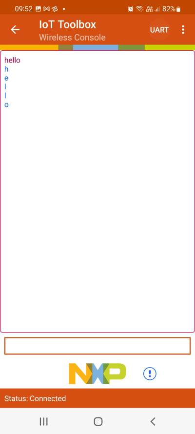
If a message is pasted into the terminal instead of typed it will appear as a longer message on the receiver side instead of single characters. Here "Hello World" is sent from A.
B:
Data received from 2C:4C:C6:F4:D3:D1 (public)(length 11):Hello World
The boards will disconnect after a while and to reconnect press the WAKEUP (SW4) button on (A) again.
Note that it is possible to switch A and B so that B is the one doing the searching. On the uCOM Carrier Board used by B, use the WAKEUP (SW5) button.
Use Case 2 – iMX RT Developer’s Kit and Android Phone
This will be showcased with
- One iMX RT1062 kit with an 1XK M.2 module (referred to as A below) and
- One Android phone with the IoT Toolbox app installed
Start the A board
A:
Built for WIFI_IW416_BOARD_MURATA_1XK_M2
BLE Wireless Uart demo start...
Bluetooth initialized
Advertising successfully started
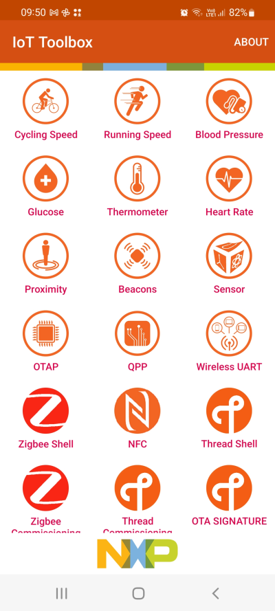
Start the IoT Toolbox app on the phone and then click the Wireless UART which will start to scan for nearby wireless UARTs and list them.
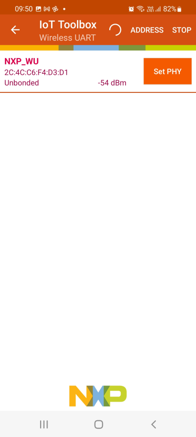
Click on the found wireless UART to open up a new view:
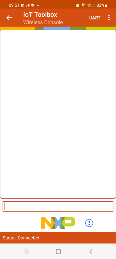
If the phone asks to connect to the device, accept it. If asked for a password/passphrase/pin code look in the terminal for (A):
Passkey for 4D:49:95:86:0C:7B (random): 304696
After entering it on the phone the two-way terminal should now work as it did between two kits.
The IoT Toolbox application can be used in combination with several of the other examples in the SDK. For more information about that, see the UM11442-NXP-Wi-Fi-and-Bluetooth-Demo-Applications-for-i.MX-RT-platforms-User-Guide.pdf that comes with the SDK.
Troubleshooting
Some things to check if the application is not working as expected:
Program not starting after being flashed
This can happen if the flash operation failed.
wlan-info
Station connected to:
"hello"
        SSID: VSG1_5G
        BSSID: 60:38:E0:9D:B6:F7
        channel: 100
        role: Infra
        security: WPA2

        IPv4 Address
        address: DHCP
                IP:             10.158.186.137
                gateway:        10.158.186.69
                netmask:        255.255.255.0
                dns1:           10.158.186.69
                dns2:           0.0.0.0

        IPv6 Addresses
        Link-Local   :  FE80::2E4C:C6FF:FEF4:D3D0 (Preferred)

uAP not started
For the tests to work the "Station connected to" message must be shown and the board must have received an IP address from DHCP. If one of those is missing check the parameters that you passed to wlan-add again.
Cannot find M.2 module
A successful detection of the M.2 module looks like this when the program starts:
Built for WIFI_IW416_BOARD_MURATA_1XK_M2
========================================
wifi cli demo
========================================
Initialize CLI
========================================
Initialize WLAN Driver
========================================
MAC Address: 2C:4C:C6:F4:D3:D0
========================================
app_cb: WLAN: received event 11
========================================
app_cb: WLAN initialized
========================================
WLAN CLIs are initialized
========================================
CLIs Available:
========================================
If the M.2 module cannot be detected, check that the module is correctly inserted. Make sure that the project has been configured for the correct M.2 module (see Step #3).
Firewalls
As with all network tests make sure that the firewall on the test PC is not stopping the traffic from the iMX RT board. This is probably not a problem when running the iperf client on the PC as it is outgoing traffic, however when running the iperf server it expects incoming connections and those may be blocked by a firewall.
Throughput
The exact speed that can be achieved during testing is heavily dependent on the test environment including but not limited to:
- Use of onboard antenna vs external antenna
- Wireless router performance
- Distance between iMX RT and router
- PC that is running the software
- Usage of the 2.4GHz/5GHz band by others
Debug Interface
It is strongly recommended using a debug/JTAG probe during program development. The low-cost LPC-Link2 or MCU-Link are excellent choices. Keil ULINK2 and ULINKplus, as well as Segger J-LINK, are also excellent debug probes.
There are two debug interface connectors available on the iMX OEM Carrier board:
J10 – this is a Cortex Debug connector. It is a 2x5 pos, 50 mil pitch connector without a shroud. Be careful when inserting the debug probe cable. Position 1 is in specifically marked on the PCB silkscreen. It is located in the lower right corner, see Figure 2 below. The connector supports both the SWD and JTAG interfaces.
J11 – this is an ARM Debug connector. It is a 2x10 pos, 100 mil pitch connector with shroud.
Both connectors are defined and supports both the SWD and JTAG type of debug interfaces.
Note that in order to enable the JTAG/SWD interface on the i.MX RT, JP5 shall not be shorted/inserted.

note
Note that due to the powering sequencing requirements on the i.MX RT family, the debug probe I/O voltage MUST follow the i.MX RT I/O voltage.
The debug adapter must not drive any output higher than the Vcc/Vref voltage (and if that voltage is zero, then the debug adapter must not drive any output signal). Vcc/Vref is pin 1 on both J10 and J11.
Make sure the debug probe does not have a fixed output voltage, but rather follow Vcc/Vref. If using LPC-Link2 as debug interface, make sure there is NO jumper inserted in JP2 on the LPC-Link2.
J-LINK/J-TRACE Support
This chapter describes the steps necessary to get the Segger J-TRACE to work with NXP MCUXpresso and Keil uVision. The same instructions are likely to work for Segger J-LINK as well, but it has not been verified.
Install J-LINK Software
Download and install the latest version of Segger's software: https://www.segger.com/downloads/jlink/
Legacy
This section has been left here for completeness but it is no longer needed with newer hardware and later versions of the software.
The software for the J-TRACE/J-LINK is installed in a central location (i.e. outside of the IDEs). The latest version (v6.60d) as of January 2020 has support for the iMX RT1062 but needs a configuration change to support the EcoXiP flash memory:
Download and install the latest version of Segger's software: https://www.segger.com/downloads/jlink/JLink_Windows.exe (v6.42, or later). The rest of the steps will use <jdir> as abbreviation for the folder that the driver was installed in, for example
c:\Program Files (x86)\SEGGER\JLink_V642b\Open
<jdir>\JLinkDevices.xmlSearch for MCIMXRT1062 to find
<Device>In each of the
<Device>entries, change
Loader="Devices/NXP/iMXRT106x/NXP_iMXRT106x_HyperFlash.elf"toLoader="Devices/NXP/iMXRT106x/NXP_iMXRT106x_QSPI.elf"
Change theMaxSize="0x04000000"toMaxSize="0x00400000"and then save the file.
Debug Troubleshooting
In some cases, the IDE complains about not being able to connect to the target. This is most likely because the program already running on the target is interfering. The solution is to put the hardware in ISP mode before starting the flash/debug operation in the IDE. To do this:
- Push and hold down the ISP enable button
- Press the Reset button
- Release the Reset button
- Wait 1 seconds
- Release the ISP enable button
If the LPC-Link2 debugger is used then there are some additional things to note:
- Make sure that the J2 jumper on the LPC-Link2 is not inserted. If the jumper is inserted/closed then the target will be powered by the LPC-Link2 which might be too much power for the USB port that the LPC-Link2 is connected to.
- If the LPC-Link2 is not found by the IDE and you are working on a laptop then try using a powered USB hub instead.
- The troubleshooting section in this forum post has a couple of additional things to try: https://community.nxp.com/thread/388964
- There is a Using and troubleshooting LPC-Link2 in the Appendix - Additional Hints and Tips of the User Guide for MCUXpresso IDE. The location of the document is
c:\nxp\MCUXpressoIDE_11.5.0_7232\MCUXpresso_IDE_User_Guide.pdfif the IDE was installed with the default settings.