iMX RT and Infineon/Cypress
Introduction
This section is a step-by-step guide to get Wi-Fi up and running in the shortest possible time:
- The first step is to download and install the SDK.
- The second step describes how to physically mount the M.2 module.
- The third step describes how to set up, modify, and run the example project.
Above are the three simple steps to get up-and-running immediately!
There are a couple of more sections describing different aspects, like debugging and a performance patch for iperf.
This document focuses only on the Cypress/Infineon based modules as the support for them was removed in SDK 2.10.0. Some SDKs will contain examples for NXP/Marvell chipsets, but those will be ignored. For information about NXP/Marvell modules see here.
NXP removed support for the 1DX, 1LV and 1MW modules in SDK 2.10.0. The table below shows the last patched SDK version for each M.2 module and if it includes Bluetooth support or not.
| CYW4343W | CYW43012 | CYW43455 | |
|---|---|---|---|
| 1DX | 1LV | 1MW | |
| SDIO | SDIO | SDIO | |
| Board | |||
| imxrt1052 | Wi-Fi: 2.8.6 BT: 2.8.6 | Wi-Fi: 2.8.6 BT: No | Wi-Fi: 2.8.6 BT: 2.8.6 |
| imxrt1062 | Wi-Fi: 2.9.3 BT: 2.9.3 | Wi-Fi: 2.9.3 BT: No | Wi-Fi: 2.9.3 BT: 2.9.3 |
| imxrt1064 1 | Wi-Fi: 2.9.2 BT: 2.9.2 | --- | Wi-Fi: 2.9.2 BT: 2.9.2 |
| imxrt1166 | --- | --- | --- |
| imxrt1176 | Wi-Fi: 2.9.2 BT: No | Wi-Fi: 2.9.2 BT: No | Wi-Fi: 2.9.2 BT: No |
| 1 Requires use of uSD-to-M.2 adapter |
Further Information
- Documents included in the
docs/folder of the NXP SDK:- Getting Started with MCUXpresso SDK for MIMXRT1170-EVK.pdf
- MCUXpresso SDK API Reference Manual_MIMXRT1176.pdf
Supported Examples
These are the examples found in the SDKs (availability may vary depending on CPU and SDK version). Note that examples ending in _43012 is for the 1LV M.2 module, _4343W is for the 1DX and _43455 is for the 1MW.
Table is for iMX RT1062 SDK 2.9.3
| Example | Description |
|---|---|
aws_shadow_wiced_* | Uses the AWS IoT framework to communicate with a "shadow" of the device in the cloud. |
wiced_iperf_* | This is a performance test application |
wiced_iperf3_* | This is a performance test application similar to the iperf above, but using a later version of the iperf protocol |
wiced_mfg_test_* | This is a special application that is used for RF measurements, and it will not be covered by this document |
wiced_webconfig_* | Example that starts of in provisioning mode where the board starts up an access point which the user can connect to. After connecting it is possible to open a URL where a list of all found Wi-Fi networks are listed. The user can then pick and configure one of the networks. The credentials are stored in the flash of the MCU and after a reboot the board connects to that Wi-Fi network instead of starting an access point. |
wiced_ble_4343W | For 1DX M.2 module. It is a Bluetooth Low Energy (BLE) + Wi-Fi application that scans for nearby Wi-Fi networks, connects to one and then advertises as a BLE devices. |
wiced_ble_43455 | For 1MW M.2 module. It is a Bluetooth Low Energy (BLE) + Wi-Fi application that scans for nearby Wi-Fi networks, connects to one and then advertises as a BLE devices. |
wiced_bt_passthrough_4343W | For 1DX M.2 module. This application allows direct communication over UART between the 1DX M.2 module and a PC. It requires the CyBluetool from Cypress to work, and it will not be covered by this document |
Step #1: Downloading and Installing MCUXpresso SDK
This section will walk you through the installation of the MCUXpresso SDK, which is a package of sample software projects (with device drivers and peripheral examples and demos) that will get you started immediately with your i.MX RT software development. Note that even though the name of the SDK suggests the code package is for the MCUXpresso IDE, the sample projects have project files for other IDEs as well, such as Keil uVision/MDK, IAR Embedded Workbench, and more.
Start by downloading the patched SDK (making sure to pick the correct version according to the table above) from this URL: https://sw.embeddedartists.com/.
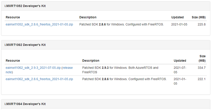
Save the file on your computer. Note the download location. The file name always contains the CPU, SDK version and release date.
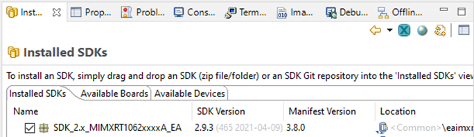
The SDK needs to be installed in MCUXpresso before it can be used. To do that start MCUXpresso and then drag-n-drop the downloaded SDK archive (eaimxrt1062_sdk_2.9.3_2021-07-05.zip) on to the "Installed SDKs" tab:
Step #2: Mount M.2 Module
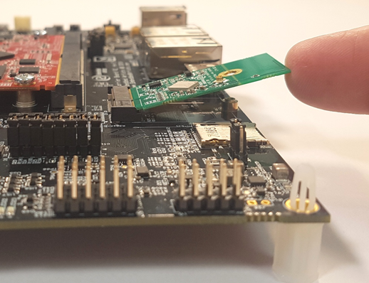
Make sure the iMX RT Developer's Kit is powered off and then mount the M.2 Module, as illustrated in the pictures below:


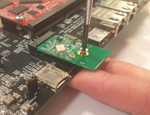
Do not put too much force/pressure on the M2 screw (into the M.2 connector stand-off) so that the PCB is bent. Bending the PCB too much will damage the board!
Use your fingers on the bottom side (while screwing) to give a counter-force, keeping the PCB straight.
The picture below illustrates the typical angle (about 25 degrees) to use when inserting the M.2 module into the connector. The pictures illustrate another carrier board, but the principle is exactly the same, regardless of carrier board.
The picture below illustrates how to use two fingers, placed under the grounding stand-off, to avoid bending the board. Make sure to always use this method to avoid damaging the board.
Step #3: Import, Configure, Run Example
Running any of the examples requires the following steps:
- Import the example
- Select which Wi-Fi solution to use
- Configure the example for your environment (e.g. SSID + password for your network)
- Compile and debug/run
Import Example
The following steps will guide you through opening the wiced_iperf_4343W application from the SDK.
- Install the SDK as described in Step #1 if you have not done so already
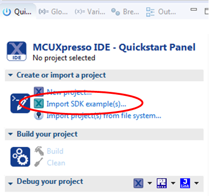
- Click the Import SDK example(s)... link in the Quickstart Panel.
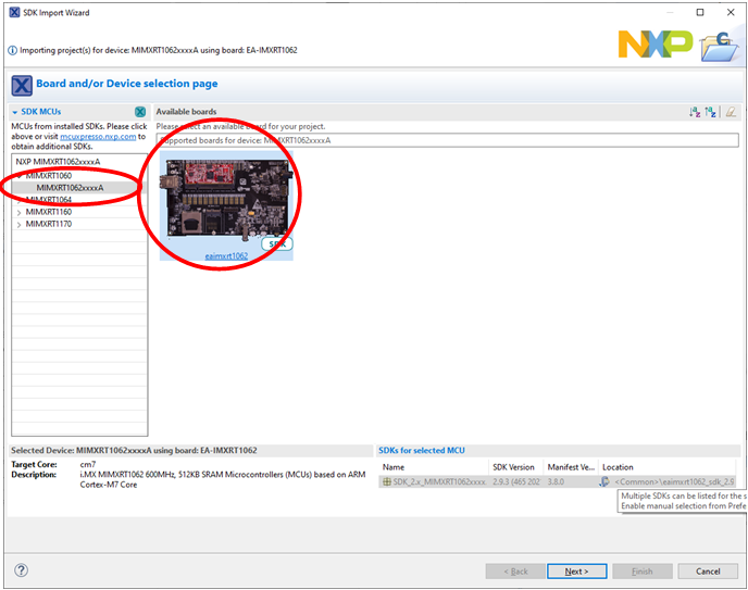
- This step will use the iMX RT1062, but the instructions are the same for any of the supported iMX RT boards. Select the MIMXRT1060 and eaimxrt1062. Click Next to go to the project selector.
- Select the
wiced_iperf_4343Wexample and make sure to switch from Semihost to UART for the SDK Debug Console.
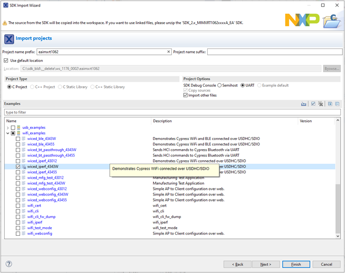
- With the changes made, click Finish to have MCUXpresso complete the project setup
Select M.2 Module
The projects for Infineon/Cypress based M.2 modules have the module name as suffix to the project name, i.e. wiced_iperf_4343W for the 1DX/4343W module, wiced_iperf_43455 for the 1MW/43455 module and wiced_iperf_43012 for the 1LV/43012 module. Pick a project with the correct suffix and it is already
configured for the M.2 module.
Configure The Example
Some Wi-Fi examples (like the wiced_webconfig_* examples) don’t need any configuration as everything is handled at runtime (searching, adding networks, connecting etc.)
However, most of the Wi-Fi examples have settings that must be configured before compiling for the program to connect to your network or to use the correct channel etc.
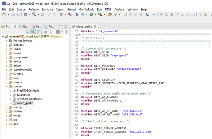
The settings are typically found in the project’s main file, like this for the wiced_iperf_4343W example:
These are some common configuration options:
| Define | Comment |
|---|---|
AP_SSID | SSID of the Access Point that the example will create |
AP_PASS | Password for the Access Point |
AP_SEC | How is the Access Point secured |
IPERF_SERVER_ADDR | IP address of the server to test against |
WIFI_SSID | SSID of the network to connect to |
WIFI_PASSWORD | Password |
WIFI_SECURITY | How is the network secured |
Compile and Run/Debug
To download and run the application, perform these steps:
- Click Build in the Quickstart Panel
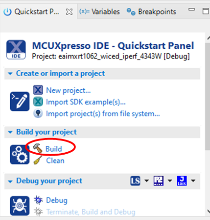
- The program builds without errors
- Connect a debug probe (LPC-Link2, ULINK2, J-LINK, MCU-Link etc.) to the iMX RT Developer’s Kit and to your PC. See chapter Debug Interface for details how to connect the debug probe
- Open the terminal application on the PC, such as TeraTerm or PuTTY, and connect to the debug serial port number. Configure the terminal with 115200 baud, 8N1. You can alter the baud rate be searching for the reference BOARD_DEBUG_UART_BAUDRATE variable in file:
board.h - Click the "Debug" button in the Quickstart Panel to download the application to the target.
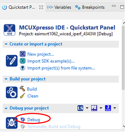
- The application is then downloaded to the target and automatically runs to the main() function.
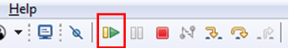
- Run the code by clicking the "Resume" button to start the application.
Explanation of one example – Wi-Fi
This will describe how to use the wiced_iperf_* examples or more specifically the wiced_iperf_4343W example which is configured for the 1DX/4343W M.2 module. For other examples, see the table in Supported Examples.
ping is a great way to test if the hardware is connected to the network, or not, but to really test the network interface it is better to use a program like iperf. Iperf requires both a server and a client to run the tests. The client is typically run on the iMX RT1062 board and the server software can either be installed on a computer on the local network (https://iperf.fr/iperf-download.php) or one of the online servers can be used (https://iperf.fr/iperf-servers.php). It is also possible to run the server on the iMX RT Developer’s Kit and the client on a PC in the same local network.
If the example name is wiced_iperf_*, make sure to select the latest version of the 2.0.x branch (2.0.9 seems to be the last released version) when downloading the iperf software from https://iperf.fr/iperf-download.php. Version 3.x is not supported by this example, and it will not work as iperf and iperf3 are completely different protocols.
If the example name is wiced_iperf3_*, make sure to select the latest version of the 3.x branch (3.1.3 seems to be the last released version) when downloading the iperf3 software from https://iperf.fr/iperf-download.php. Version 2.x is not supported by this example, and it will not work as iperf and iperf3 are completely different protocols.
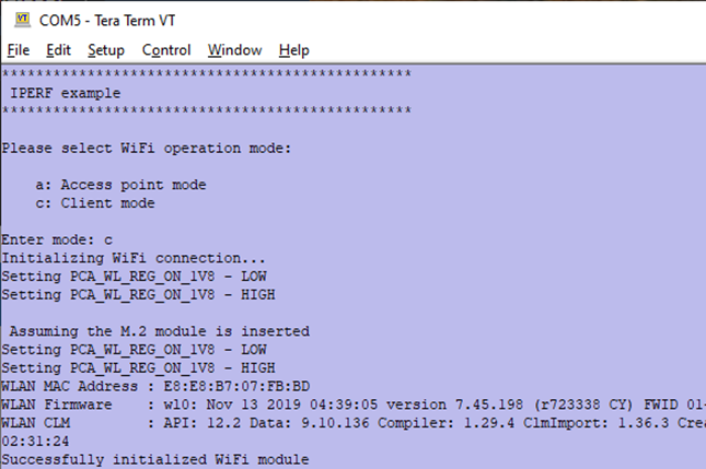
The wiced_iperf_4343W example presents a very basic shell in the terminal in which you can control what happens. When the program starts it will show this in the terminal:
************************************************
 IPERF example
************************************************

Please select WiFi operation mode:

    a: Access point mode
    c: Client mode

Enter mode:
Make sure that the project has been configured with the network details and the IPERF_SERVER_ADDR as explained in Step #3.
After setting up an Access Point or connecting to the configured network, the example will show the different modes of testing:
Successfully joined: VSG1_5G
Getting IP address from DHCP server
 IPv4 Address got from DHCP  : 10.158.186.136

Please select one of the following modes to run IPERF with:

    1: TCP server mode (RX only test)
    2: TCP client mode (TX only test)
    3: TCP client dual mode (TX and RX in parallel)
    4: TCP client tradeoff mode (TX and RX sequentially)
    5: UDP server mode (RX only test)
    6: UDP client mode (TX only test)
    7: UDP client dual mode (TX and RX in parallel)
    8: UDP client tradeoff mode (TX and RX sequentially)

Enter mode number:
The list of modes may vary depending on SDK version.
Mode 1 - Server RX Only
Type a 1 to start server mode. Check the IP number that was assigned (in this case 10.158.186.136 as shown above)
and then run the following command on the PC (the program exists for most common operating systems but is shown here for Windows):
C:\temp> iperf -c 10.158.186.136 -i 2 -t 20 -P 4
The parameters specify the IP number of the iMX RT board, that a report should be printed every 2 seconds, that the test will run for 20 seconds and use 4 threads/connections.
After the test completes it will print something like this on the PC:
[SUM] 0.0-20.0 sec 95.5 MBytes 40.0 Mbits/sec
The log from the iMX RT will show something like this for each of the 4 connections after the test completes:
-------------------------------------------------
 TCP_DONE_SERVER (RX)
 Local address : 10.158.186.136  Port 5001
 Remote address : 10.158.186.131  Port 60430
 Bytes Transferred 25034776
 Duration (ms) 20464
 Bandwidth (kbitpsec) 9786
The information shown on the target is not entirely correct. It shows the correct number of bytes transferred but does not calculate the time correctly. As seen above the time is 20464ms for a test that takes 20 seconds. The wiced_iperf code measures time from the connection is established and not from the first byte is sent over the connection. Depending on the PC software it may take extra time (in this case roughly 0.4 seconds) to set up the test and this should not be included in the test result, but it is. When checking the result look at the PC instead of the target (i.e., the iMX RT1062).
Press SPACE to return to the main menu to run this or another test again.
Mode 2 - Client TX Only
Before running this test the PC must be running the server:
C:\temp> iperf -s
------------------------------------------------------------
Server listening on TCP port 5001
TCP window size:  128 KByte (default)
------------------------------------------------------------
Type a 2 to start client mode. It will run the tests against the server IP number configured in Step #3.
Make sure that the IPERF_SERVER_ADDR matches the IP number of the PC running the server.
After the test completes (it takes 10 seconds) it will print the something like this:
# -------------------------------------------------
TCP_DONE_CLIENT (TX)
 Local address : 10.158.186.136  Port 49153
 Remote address : 10.158.186.131  Port 5001
 Bytes Transferred 29429244
 Duration (ms) 10000
 Bandwidth (kbitpsec) 23543
Press SPACE to return to the main menu to run this or another test again.
Mode 3 - Client RX+TX in Parallel
Before running this test the PC must be running the server:
C:\temp> iperf -s
------------------------------------------------------------
Server listening on TCP port 5001
TCP window size:  128 KByte (default)
------------------------------------------------------------
Type a 3 to start client mode. It will run the tests against the server IP number configured in Step #3.
Make sure that the IPERF_SERVER_ADDR matches the IP number of the PC running the server.
After the test completes (it takes 10 seconds) it will print the something like this:
# -------------------------------------------------
TCP_DONE_CLIENT (TX)
 Local address : 10.158.186.136  Port 49154
 Remote address : 10.158.186.131  Port 5001
 Bytes Transferred 6862024
 Duration (ms) 10000
 Bandwidth (kbitpsec) 5489

# -------------------------------------------------
TCP_DONE_CLIENT (RX)
 Local address : 10.158.186.136  Port 5001
 Remote address : 10.158.186.131  Port 59354
 Bytes Transferred 38795876
 Duration (ms) 10481
 Bandwidth (kbitpsec) 29612
Press SPACE to return to the main menu to run this or another test again.
Mode 4 - Client RX+TX in Sequence
Before running this test the PC must be running the server:
C:\temp> iperf -s
------------------------------------------------------------
Server listening on TCP port 5001
TCP window size:  128 KByte (default)
------------------------------------------------------------
Type a 4 to start client mode. It will run the tests against the server IP number configured in Step #3.
Make sure that the IPERF_SERVER_ADDR matches the IP number of the PC running the server.
After the test completes (it takes 10 seconds) it will print the something like this:
# -------------------------------------------------
TCP_DONE_CLIENT (TX)
 Local address : 10.158.186.136  Port 49155
 Remote address : 10.158.186.131  Port 5001
 Bytes Transferred 28877364
 Duration (ms) 10001
 Bandwidth (kbitpsec) 23099

# -------------------------------------------------
TCP_DONE_CLIENT (RX)
 Local address : 10.158.186.136  Port 5001
 Remote address : 10.158.186.131  Port 59356
 Bytes Transferred 43252324
 Duration (ms) 10380
 Bandwidth (kbitpsec) 33335
Press SPACE to return to the main menu to run this or another test again.
Mode 5 to 8 - UDP
The first four modes were for TCP and modes 5 through 8 are for UDP. The tests are run in the same way except
for one thing: the -u option must be used on the PC side to force iperf into UDP mode.
C:\temp> iperf -s -u
------------------------------------------------------------
Server listening on UDP port 5001
UDP buffer size:  176 KByte (default)
------------------------------------------------------------
or
C:\temp> iperf -u -c 10.158.186.136 -i 2 -t 20 -P 4
Explanation of one example – Bluetooth
This will describe how to use the wiced_ble_* examples or more specifically the wiced_ble_43455 example which is configured for the 1DX/4343W M.2 module. For other examples, see the table in Supported Examples.
The example will start by scanning for nearby Wi-Fi networks and show some information about each network that is found.
It will then connect to the Wi-Fi network specified in Step #3.
When the network connection has been established it will start BLE advertising with the device name mcuxpresso-hello-sensor. Download and install one of the following apps on your phone:
- nRF Connect: https://play.google.com/store/apps/details?id=no.nordicsemi.android.mcp
- LightBlue: https://play.google.com/store/apps/details?id=com.punchthrough.lightblueexplorer
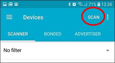
Start the nRF Connect app and press the SCAN button:
The Bluetooth device should appear like this:
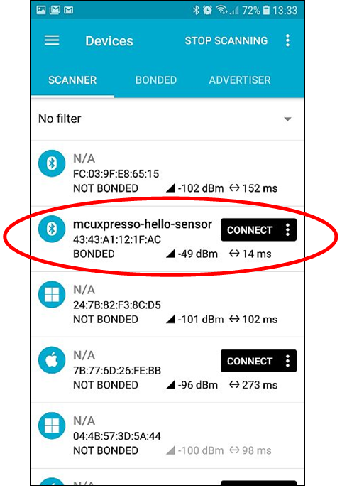
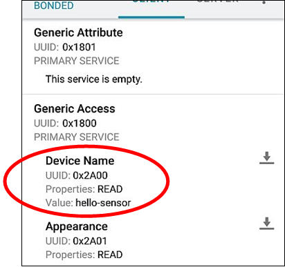
Click CONNECT to get a list of attributes and information like this:
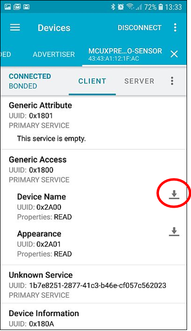
Click the marked button to read the device name. It will look like this:
Troubleshooting
Some things to check if the application is not working as expected:
Program not starting after being flashed
This can happen if the flash operation failed.
Cannot find M.2 module
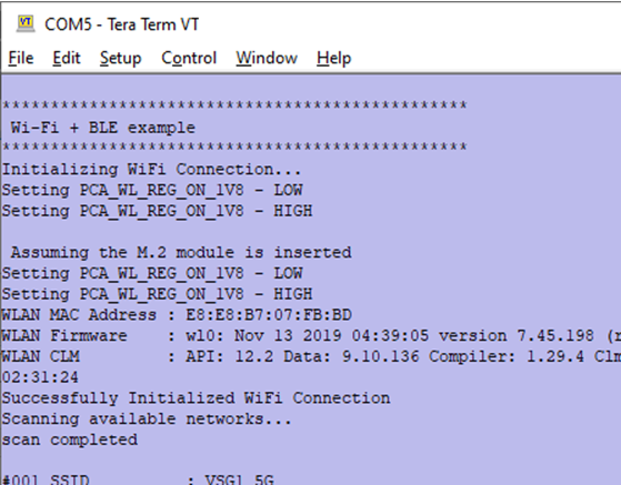
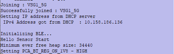
A successful detection of the M.2 module looks like this (in a Wi-Fi example):
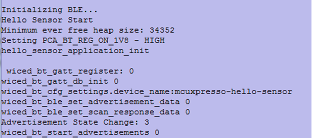
A successful detection of the M.2 module looks like this (in a Bluetooth example):
If the M.2 module cannot be detected, check that the module is correctly inserted (see Step #2). Make sure that the project has been configured for the correct M.2 module (see Step #3).
Firewalls
As with all network tests make sure that the firewall on the test PC is not stopping the traffic from the iMX RT board. This is probably not a problem when running the iperf client on the PC as it is outgoing traffic, however when running the iperf server it expects incoming connections and those may be blocked by a firewall.
Throughput
The exact speed that can be achieved during testing is heavily dependent on the test environment including but not limited to:
- Use of onboard antenna vs external antenna
- Wireless router performance
- Distance between iMX RT and router
- PC that is running the software
- Usage of the 2.4GHz/5GHz band by others
Debug Interface
It is strongly recommended using a debug/JTAG probe during program development. The low-cost LPC-Link2 or MCU-Link are excellent choices. Keil ULINK2 and ULINKplus, as well as Segger J-LINK, are also excellent debug probes.
There are two debug interface connectors available on the iMX OEM Carrier board:
-
J10 – this is a Cortex Debug connector. It is a 2x5 pos, 50 mil pitch connector without a shroud. Be careful when inserting the debug probe cable. Position 1 is in specifically marked on the PCB silkscreen. It is located in the lower right corner, see Figure 2 below. The connector supports both the SWD and JTAG interfaces.
-
J11 – this is an ARM Debug connector. It is a 2x10 pos, 100 mil pitch connector with shroud.
Both connectors are defined and supports both the SWD and JTAG type of debug interfaces.
Note that in order to enable the JTAG/SWD interface on the i.MX RT, JP5 shall not be shorted/inserted.

Note that due to the powering sequencing requirements on the i.MX RT family, the debug probe I/O voltage MUST follow the i.MX RT I/O voltage.
The debug adapter must not drive any output higher than the Vcc/Vref voltage (and if that voltage is zero, then the debug adapter must not drive any output signal). Vcc/Vref is pin 1 on both J10 and J11.
Make sure the debug probe does not have a fixed output voltage, but rather follow Vcc/Vref. If using LPC-Link2 as debug interface, make sure there is NO jumper inserted in JP2 on the LPC-Link2.
J-LINK/J-TRACE Support
This chapter describes the steps necessary to get the Segger J-TRACE to work with NXP MCUXpresso and Keil uVision. The same instructions are likely to work for Segger J-LINK as well, but it has not been verified.
Install J-LINK Software
The software for the J-TRACE/J-LINK is installed in a central location (i.e. outside of the IDEs). The latest version (v6.60d) as of January 2020 has support for the iMX RT1062 but needs a configuration change to support the EcoXiP flash memory:
-
Download and install the latest version of Segger's software: https://www.segger.com/downloads/jlink/JLink_Windows.exe (v6.42, or later). The rest of the steps will use <jdir> as abbreviation for the folder that the driver was installed in, for example
c:\Program Files (x86)\SEGGER\JLink_V642b\ -
Open
<jdir>\JLinkDevices.xml -
Search for MCIMXRT1062 to find
<Device> -
In each of the
<Device>entries, change
Loader="Devices/NXP/iMXRT106x/NXP_iMXRT106x_HyperFlash.elf"toLoader="Devices/NXP/iMXRT106x/NXP_iMXRT106x_QSPI.elf"
Change theMaxSize="0x04000000"toMaxSize="0x00400000"and then save the file.
Debug Troubleshooting
In some cases, the IDE complains about not being able to connect to the target. This is most likely because the program already running on the target is interfering. The solution is to put the hardware in ISP mode before starting the flash/debug operation in the IDE. To do this:
- Push and hold down the ISP enable button
- Press the Reset button
- Release the Reset button
- Wait 1 seconds
- Release the ISP enable button
If the LPC-Link2 debugger is used then there are some additional things to note:
- Make sure that the J2 jumper on the LPC-Link2 is not inserted. If the jumper is inserted/closed then the target will be powered by the LPC-Link2 which might be too much power for the USB port that the LPC-Link2 is connected to.
- If the LPC-Link2 is not found by the IDE and you are working on a laptop then try using a powered USB hub instead.
- The troubleshooting section in this forum post has a couple of additional things to try: https://community.nxp.com/thread/388964
- There is a Using and troubleshooting LPC-Link2 in the Appendix - Additional Hints and Tips of the User Guide for MCUXpresso IDE. The location of the document is
c:\nxp\MCUXpressoIDE_11.5.0_7232\MCUXpresso_IDE_User_Guide.pdfif the IDE was installed with the default settings.
Improved IPERF performance
There are some improvements that can be made to the wiced_iperf_* examples to more than double the throughput. The changes include rearranging the memory layout, increasing the TCP receive window and increasing the number of buffers.
The instructions below were written for an older version of the SDK. As of 2.7.0 the memory ranges and buffers have been modified and as a result the instructions below will result in a too big binary that cannot be used. The instructions are left here as pointers for the reader that wants to experiment with performance tweaking themselves.
-
Setup the
wiced_iperfexample as explained in Step #3 and the example explanation and verify that it works -
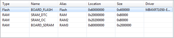
Right-click the project and select Properties... from the menu. Expand the tree and locate the MCU Settings node:
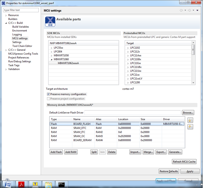
Delete the SRAM_ITC and then change the sizes of SRAM_DTC and SRAM_OC so that it looks like below and then save the changes and close the dialog
- Open
board/board.cand locate these lines that control the size of theSRAM_DTC(region 5):

Replace the ARM_MPU_REGION_SIZE_128KB with ARM_MPU_REGION_SIZE_512KB. This aligns the size with the 0x80000 value entered in the previous dialog for SRAM_DTC.
- Open
source/lwipopts.hand locate these lines:
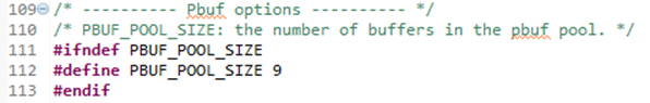
Change from 9 to 44 buffers in the pool. This is what the increase of SRAM_DTC was used for.
- In the same file (
source/lwipopts.h) locate these lines:
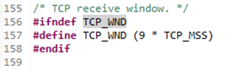
Replace the constant 9 with 44
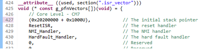
- Open
startup/startup_mimxrt1062.cand locate these lines:
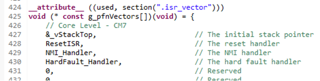
Replace the &_vStackTop with (0x20200000 + 0x1000U) to move the initial stack pointer to the end of the first block of SRAM_OC. It should look like this after the change:
- In the same file (
startup/startup_mimxrt1062.c) locate theResetISRfunction:
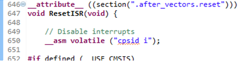
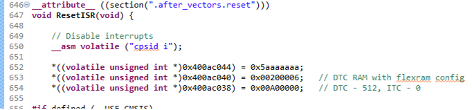
Insert the following lines after the _asm... line:
*((volatile unsigned int *)0x400ac044) = 0x5aaaaaaa;
*((volatile unsigned int *)0x400ac040) = 0x00200006;   // DTC RAM with flexram config
*((volatile unsigned int *)0x400ac038) = 0x00A00000;   // DTC - 512, ITC - 0
so that it now looks like this:
- Compile and run. Compare iperf throughput results with, and without, this patch.