iMX Developer’s Kit Differences (V2 vs V3)
For most purposes there is very little difference between the V2 and V3 of iMX Developer’s Kits. The table below lists the differences. The major differences are; V2 kits have an audio codec and more advanced M.2 debug support. V3 kits support the new M.2 pin definition where pin 40 (instead of pin 66) is used to allow the host processor to wake the Wi-Fi chipset.
| iMX Developer's Kit V2 | iMX Developer's Kit V3 |
|---|---|
 |  |
| Datasheet and Schematic download: https://www.embeddedartists.com/products/com-carrier-board-v2/ | Datasheet and Schematic download: https://www.embeddedartists.com/products/ucom-carrier-board/ |
Advanced debug features on M.2 interface (described in more detail in section about COM Carrier Board):
| Standard debug features with current measurement and JTAG signals acessible. For more details, see section about uCOM Carrier Board |
| On-board audio codec | No on-board audio codec |
M.2 pinning:
WL_DEV_WAKE has been depreciated and changed to pin 40 in an updated pinning definition. | Both M.2 pins 40 and 66 can be used as WL_DEV_WAKE, to support a smooth transition of the M.2 pinning standard. |
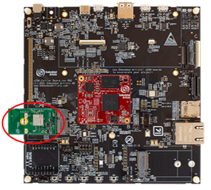
uCOM Carrier Board (aka iMX Developer’s Kit V3) Features
The uCOM Carrier Board (used on iMX Developer’s Kits V3) is a reference implementation of the M.2 interface. This section describes the features of the design.
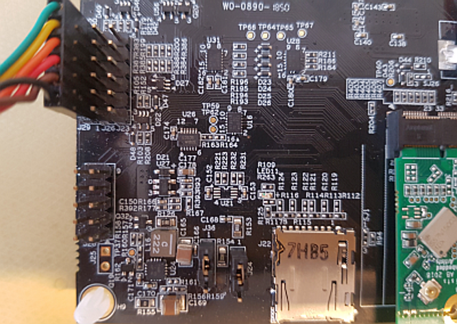
The picture below illustrates the main M.2 connector, J33, and related jumpers on the uCOM Carrier Board.

The M.2 E-key interface has SDIO, USB, UART, I2S (audio), I2C and PCIe interfaces defined, and all are connected. M.2 E-key modules mainly implements a Wi-Fi/BT or NFC interface. The connector supports 2230-sized M.2 modules.
There are several features and functions of the M.2 E-key interface that has been added to be able to do professional evaluation/benchmarking and debugging. These will be addressed in the following subsections.
VBAT Powering
There is a separate 3.3V / 3A VBAT power supply that is dedicated to the M.2 interface. The default output voltage is 3.3V but it is possible to change it to 3.6V by removing a resistor. Setting VBAT to 3.6V can improve radio performance on the M.2 module. Note that setting VBAT to 3.6V is outside of the M.2 specification, but if the radio chip/module on the M.2 module can handle VBAT set to 3.6V then it can be an option to measure/evaluate the added performance.
VBAT Current Measurement
It is possible to measure the VBAT current to the M.2 module. JP29 is connected over series resistor R236 that powers the M.2 connector, J33. Note that R236 is a zero-ohm resistor per default. To measure the current, R236 must be replaced with a suitable resistor. Selecting a suitable value is a trade-off between measurement resolution and voltage drop. It is recommended to keep the voltage drop below 100mV. Also remember that there can be current spikes (up to about 1 Amp) during for example startup calibration. A value between 50-100 milliohm can be a good starting point.
Bluetooth UART Voltage Level (UART-C)
The Bluetooth UART channel has different voltage levels on different uCOM boards. With jumper JP30 it is possible to select either 3.3V or 1.8V level:
- iMX8M Mini/Nano has 3.3V and this is the default setting (JP30 in 1-2 position).
- iMX7ULP has 1.8V (JP30 in 2-3 position).
Audio Signal Voltage Level
The audio interface has different voltage levels on different EAuCOM boards. With jumper JP31 it is possible to select either 3.3V or 1.8V level:
- iMX8M Mini/Nano has 1.8V (JP31 in 1-2 position).
- iMX7ULP has 3.3V (JP31 in 2-3 position).
The audio source of the audio signals interface of the M.2 connector comes from the Bluetooth module (on the mounted M.2 module). This audio interface connects to the audio interface of EAuCOM boards. There is no audio codec on the uCOM Carrier Board. This can be added via the expansion connector. A realistic use case is to either connect the audio interface signals directly to an audio codec or having the EAuCOM board interface an audio codec.
JTAG Debug Channel
In collaboration with Murata, NXP, Infineon/Cypress and Embedded Artists several pins on the M.2 connector have been defined to carry JTAG signals to the chipset on the M.2 module. Note that not all M.2 modules support this debug interface.
JP33 is a JTAG debug interface to the chipset on the M.2 module.
Note that using the JTAG debug interfaces requires understanding and access to the firmware.
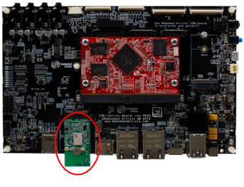
COM Carrier Board V2 Advanced Features
There are several advanced and unique features of the COM Carrier Board V2 that has been added to be able to professional evaluation/benchmarking and debugging. This section describes these features.
The picture below illustrates the different connectors and jumpers located in the lower left corner of the COM Carrier Board V2.

VBAT Current Measurement
It is possible to measure the VBAT current to the M.2 module exactly.
- Option #1, lift the short jumper (in 1-2 position) and use an external current meter to measure the current exactly, with the resolution possible with the selected meter. Note: make sure the current meter does not add a voltage drop more than 50-100mV maximum.
- Option #2, move the short jumper to position 2-3. This will add a 50 milliOhm series resistor, and it is possible to measure the voltage over this series resistor on pos 1 and 3.
Do not forget to move the short jumper back to position 1-2 after a measurement session.
VBAT 3.3V or 3.6V
It is possible to set VBAT to either 3.3V or 3.6V during run time. This is controlled via a I2C mapped GPIO. Setting VBAT to 3.6V can improve radio performance on the M.2 module. Note that setting VBAT to 3.6V is outside of the M.2 specification, but if the radio chip/module on the M.2 module is known to handle VBAT set to 3.6V then it can be an option to measure the added performance.
Support for 3.3V IO logic level (if M.2 module supports it)
The M.2 standard defines the IO voltage logic levels to a mixture of 1.8V and 3.3V. It is possible to set the 1.8V logic signals to 3.3V logic level during run time. This is controlled via an I2C mapped GPIO. Note that before doing this make sure the M.2 module used supports this feature. Not all of them do this.
Also note that this control only affects the controls signals that have 1.8V logic level, not the SDIO bus. The SDIO bus voltage level is controlled via other means.
Bluetooth UART Interception
It is possible to intercept/overtake the Bluetooth UART communication via connector J29. Insert a UART-to-USB bridge cable from FTDI (TTL-232R-3V3) into J29 and use a PC application to communicate directly with the Bluetooth part of the M.2 module.
Cypress has a tool called CyBluetool that can be used to debug Bluetooth communication problems. The program and instructions on how to use it can be downloaded here: https://community.cypress.com/docs/DOC-16475.
CyBluetool requires direct control of the UART, and this is normally controlled by Linux. The UART is different for different COM boards:
| COM boards | Bluetooth UART | Serial for U-Boot command |
|---|---|---|
| iMX6 SoloX COM | /dev/ttymxc1 | serial1 |
| iMX6 Quad COM | /dev/ttymxc4 | serial4 |
| iMX6 DualLite COM | /dev/ttymxc4 | serial4 |
| iMX6 UltraLite COM | /dev/ttymxc1 | serial1 |
| iMX7 Dual COM | /dev/ttymxc1 | serial1 |
| iMX7 Dual uCOM | /dev/ttymxc1 | serial1 |
| iMX7 ULP uCOM | /dev/ttyLP2 | serial2 |
| iMX7 ULP uCOM with on-board 1LV | Not externally accessible | Not externally accessible |
| iMX8M COM | /dev/ttymxc1 | serial1 |
| iMX8M Mini uCOM | /dev/ttymxc0 | serial0 |
| iMX8M Mini uCOM with on-board Wi-Fi/BT | Not externally accessible | Not externally accessible |
| iMX8M Nano uCOM | /dev/ttymxc0 | serial0 |
| iMX8M Nano uCOM with on-board Wi-Fi/BT | Not externally accessible | Not externally accessible |
To disable that control:
- Start the terminal program on the PC
- Power on the board
- Press space as soon as text appears in the terminal program to stop in the U-Boot
- Run this command:
setenv cmd_custom fdt set serial1 status disabled\;fdt set /modem-reset status disabled
Note that this is one line.
The serial1 part of the command is COM board specific. Replace with the correct one for your board according to the table above.
5. Run this command to save the setting:
saveenv
- Power off the board
- Insert an FTDI cable in connector J29
- Power On the board and let it boot into Linux
- Now that Linux is no longer in control of the UART the reset signal must be manually controlled. To enable Bluetooth, run the following commands to control
BT_REG_ON:
echo 496 > /sys/class/gpio/export
echo high > /sys/class/gpio/gpio496/direction
- This step is only if you are using an i.MX6 Quad or i.MX6 DualLite COM board. These two boards require the CTS signal to be pulled low:
echo 165 > /sys/class/gpio/export
echo low > /sys/class/gpio/gpio165/direction
- Follow the instruction in the CyBluetool document.
The gpio commands are not persistent and must be executed again after a reboot. The U-Boot commands are however persistent and will disable the Linux access to the UART after each reboot. To return to normal use of the UART stop in the U-Boot and run these two commands:
setenv cmd_custom
saveenv
Dual UART Debug Channels and JTAG
In collaboration with Murata, NXP, Infineon/Cypress and Embedded Artists several pins on the M.2 connector have been defines to carry UART debug channels as well as JTAG signals to the chipset on the M.2 module. Note that not all M.2 modules support all debug channels.
Connector J26 carries the Wi-Fi UART debug channel. Connect a UART-to-USB bridge cable from FTDI (TTL-232R-3V3) into J26 and use a PC terminal application to get access to the debug interface.
Connector J23 carries the Bluetooth UART debug channel. Connect a UART-to-USB bridge cable from FTDI (TTL-232R-3V3) into J26 and use a PC terminal application to get access to the debug interface.
J28 is a JTAG debug interface to the chipset on the M.2 module.
Note that using these debug interfaces typically requires understanding and access to the firmware