7-inch HDMI display kit
Introduction
This guide provides you with step-by-step instructions for how get started with the 7-inch HDMI Display Kit together with Embedded Artists iMX6, iMX7 and iMX8 based COM boards.
The philosophy behind the Display Kit is to have one common display for all iMX Developer's Kit. The display is useful for initial prototyping and proof-of-concept tests. Instead of spending time on connecting (maybe creating an adapter board) a specific display with the resolution that is planned to be used in the final design, the 7-inch HDMI Display Kit can be used right out-of-the-box.
Select a display resolution that is supported (see this guide under respective (u)COM board) and that is closest to the planned resolution. Little is gained to have the exact resolution, at least not during initial testing. It is however important to have a relatively close resolution so that the system load for creating the display data is approximately correct.
The display performs scaling on the incoming display data to the native 1024x600 pixel resolution. Some fine (pixel) details may be lost in this scaling but that is rarely critical during initial testing.
There is no need to interface the final display until the design of the carrier board. This way of working will save you time and resources!
Setup hardware
7-inch HDMI display kit
All the instructions are based on using the 7-inch HDMI display kit (EAD00363 or EAD00369) from Embedded Artists.
The 7-inch HDMI display kit comes with the following content:
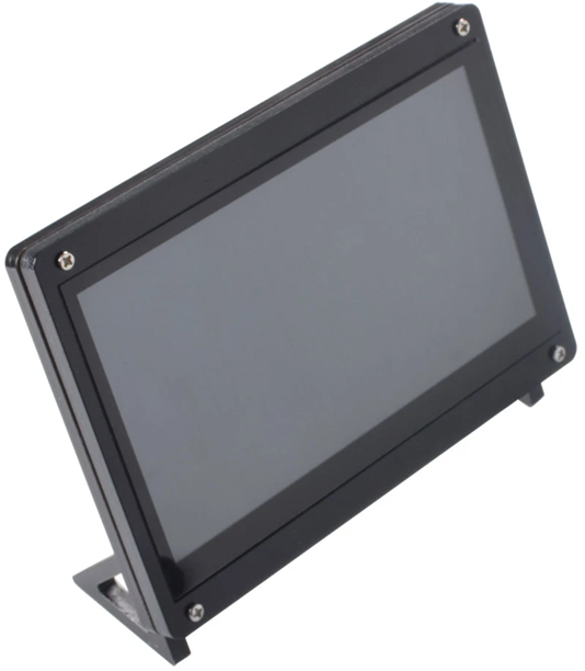
- 7-inch display mounted in a frame
- 2x micro-B to A USB cables
- 1x HDMI cable
- 1x RGB-to-HDMI adapter board (Note: only included with EAD00369).
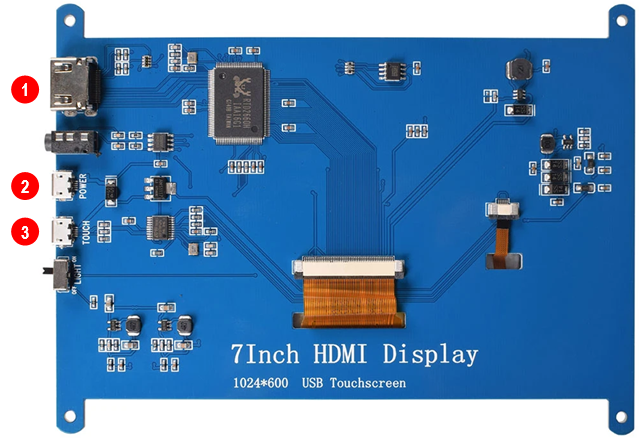
See the figure below for the location of important connectors on the display. The table describes these connectors
| Number | Connector | Description |
|---|---|---|
| 1 | HDMI connector | Connect to the HDMI connector on the carrier board or to RGB-to-HDMI adapter for boards that require this adapter (see the RGB-to-HDMI adapter section). |
| 2 | Power | For powering, connect micro-B to A USB cable to an external USB hub, your computer or to USB port on carrier board. See the Powering section for details about powering. |
| 3 | Touch | Connect micro-B to A USB cable to USB port on carrier board, see the Touch Interface section for details. |
Optional RGB-to-HDMI adapter
The following COM boards require you to use the RGB-to-HDMI adapter (included with EAD00369) between the Developer’s Kit and the display.
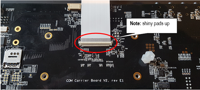
First connect the flat cable to the J39 connector on the COM Carrier Board V2 as shown in the figure below.
Secondly connect the flat cable to the RGB-to-HDMI adapter as shown in the figure below.
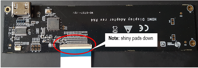
You can now connect the HDMI cable between the HDMI connector (J5) on the adapter and the HDMI connector on the display.
Touch interface - USB port on carrier board
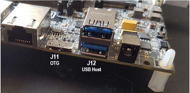
The touch interface should for most of the COM boards be connected to the USB Host Type A connector (J12) on the carrier board V2, see figure below.
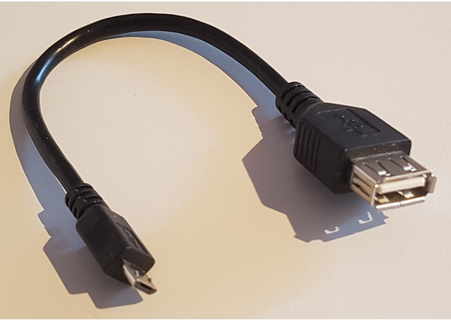
For iMX7ULP uCOM and for iMX8M Nano uCOM you however have to use connector J11 instead since these boards only have one USB interface. To be able to use J11 you need a micro-B (male) to USB A (female) adapter similar to the one shown in the second figure below.
Powering
The 7-inch HDMI Display is powered with +5V DC over the USB connectors. It requires about 500 mA current (but with a powerup current surge of up to 800mA). There are three ways of powering:
- From the COM Carrier Board's USB Host interface (requires a small rework to increase current limit )
- From a USB interface on a PC/laptop or simple USB charger.
- From a USB hub.
Rework of COM Carrier Board rev E1 USB Hub Current Limit
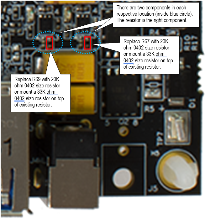
The default design limits the current on each USB Host interface to 500mA. Due to the initial current surge at power-up, a small rework is needed to increase the current limit to 1.15A. See picture below to locate R67 and R69 (in corner where the dual USB Host connector is located. The resistors shall change to 20K ohm. Alternatively, a 33K ohm resistor is mounted on top of the existing resistor. It is recommended to rework both resistors so that both USB Host connectors have the same current limit.
Connecting
The picture below illustrates how to connect the 7-inch HDMI Display. One HDMI cable is always needed. One USB cable is needed for the touch interface and optional powering. A second USB cable is needed if an alternative power source is needed.
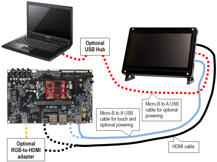
The HDMI cable shall be connected directly to the HDMI connector on the COM Carrier Board for:
- iMX6 DualLite COM
- iMX6 Quad COM
- iMX8M Mini uCOM
- iMX8M Nano uCOM
- iMX8M COM
- iMX7ULP uCOM
The optional RGB-to-HDMI adapter is needed for:
- iMX7 Dual COM
- iMX7 Dual uCOM
- iMX6 SoloX COM
- iMX6 UltraLite COM
Get up-and-running
This section contains one subsection with instructions for each supported COM board. Go to the subsection for the COM board you are using.
The instructions have been tested with Embedded Artists official ea-image-base builds that can be downloaded from https://sw.embeddedartists.com. Versions 4.14.98 and 5.4.24 were tested when writing these instructions.
iMX8M Mini uCOM
Instructions
For this board there is a MIPI-to-HDMI bridge on the uCOM adapter so you can connect the HDMI cable between the HDMI connector (J13) on the carrier board and the HDMI connector on the display.
-
Let the board boot into Linux.
-
Login using user:
rootand password:pass. -
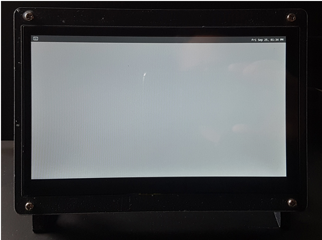
You will see the Weston desktop on the display, see the figure below.
Resolutions
The following resolutions have been tested and known to work. See the Change resolution section for instructions of how to change the resolution.
- 1920x1080@60
- 1280x720@60
- 800x600
- This resolution doesn’t work by modifying Weston.ini, only by setting the kernel parameter video=800x600, see Change resolution section below.
iMX8M Nano uCOM
Instructions
For this board there is a MIPI-to-HDMI bridge on the uCOM adapter so you can connect the HDMI cable between the HDMI connector (J13) on the carrier board and the HDMI connector on the display.
- Let the board boot into Linux.
- Login using user:
rootand password:pass. - You will see the Weston desktop on the display.
Resolutions
The following resolutions have been tested and known to work. See the Change resolution section for instructions of how to change the resolution.
- 1920x1080@60
- 1280x720@60
- 800x600@75
- 720x576@50 (only available when using 4.14.98)
- 720x480@60 (only available when using 4.14.98)
iMX8M COM
Instructions
This board has direct support for HDMI display interfaces. Connect the HDMI cable between the HDMI connector (J13) on the carrier board and the HDMI connector on the display.
- Let the board boot into Linux.
- Login using user:
rootand password:pass. - You will see the Weston desktop on the display.
Resolutions
The following resolutions have been tested and known to work. See the Change resolution section for instructions of how to change the resolution.
- 1920x1080@60
- 1280x720@60
- 720x576@50
- 720x480@60
iMX6 Quad COM / iMX6 DualLite COM
Instructions
This board has direct support for HDMI display interfaces. Connect the HDMI cable between the HDMI connector (J13) on the carrier board and the HDMI connector on the display.
-
Boot into U-Boot and enter the commands below.
infoFrom the ea-5.15.32 distribution
eadispis no longer supported. HDMI is enabled in the kernel.- Enable the HDMI interface
eadisp enable hdmi- Save changes and boot into Linux
saveenv
boot -
Let the board boot into Linux.
-
Login using user:
rootand password:pass. -
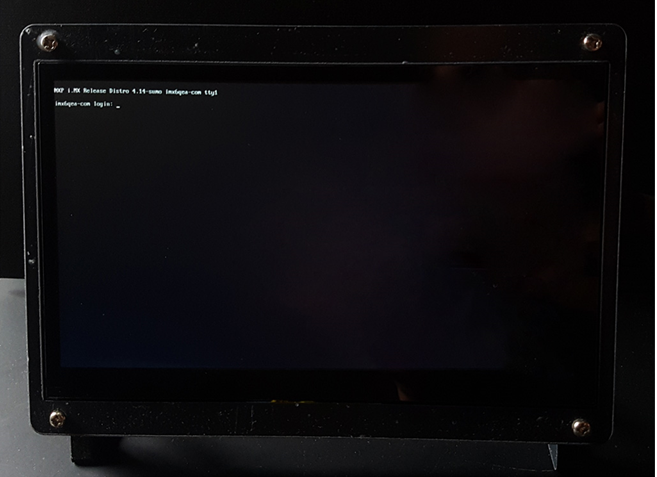
You will see the console on the display, see the figure below.
Resolutions
The following resolutions have been tested and known to work. See the Change resolution section for instructions of how to change the resolution.
- 1920x1080
- 1280x720
- 720x576
- 720x480
- 640x480
iMX6 SoloX COM
Instructions
This board supports RGB display interface which means that you must use the RGB-to-HDMI adapter as described in the RGB-to-HDMI adapter section.
From the ea-5.15.32 distribution eadisp is no longer supported. The 7-inch HDMI display together with the RGB-to-HDMI bridge is considered default display solution. All you need to do is to run the first command below where the bridge is enabled (and saveenv to save changes. ).
- Boot into U-Boot and enter the commands below.
- Enable the sii902x device (RGB-to-HDMI bridge).
setenv cmd_custom fdt set i2c0/sii902x status okay\;fdt set /sii902x-reset status okay- Enable the RGB display interface.
eadisp enable rgb- Add a new display configuration.
eadisp add rgb "DMTFT70:24:33336667,1280,720,89,164,75,75,10,10,0,0,1,0"- Check which number the new configuration got (in this case it was 12).
eadispAvailable display configurations:
0) lvds0 hannstar:18:64998375,1024,768,220,40,21,7,60,10,0,0,0,0
1) lvds0 lp101wh4_X11:24:72051300,1360,768,80,48,14,3,32,5,0,0,1,0
2) lvds0 lp101wh4:24:72332730,1366,768,80,48,14,3,32,5,0,0,1,0
3) lvds0 nhd-10.1-1024600af:24:51208521,1024,600,160,160,23,12,0,0,0,0,1,0
4) rgb Innolux-AT070TN:24:33336667,800,480,89,164,75,75,10,10,0,0,1,0
5) rgb nhd-4.3-480272ef:24:9009009,480,272,2,2,2,2,41,10,0,0,1,0
6) rgb nhd-5.0-800480tf:24:29232073,800,480,40,40,29,13,48,3,0,0,1,0
7) rgb nhd-7.0-800480ef:24:29232073,800,480,40,40,29,13,48,3,0,0,1,0
8) rgb umsh-8864:24:9061007,480,272,20,20,20,20,3,3,0,0,1,0
9) rgb umsh-8596-30t:24:33264586,800,480,128,120,20,20,8,5,0,0,1,1
10) rgb umsh-8596-33t:24:32917475,800,480,200,200,45,45,1,1,0,0,1,1
11) rgb rogin-rx050a:24:32917475,800,480,200,200,45,45,1,1,0,0,1,0
12) rgb DMTFT70:24:33336667,1280,720,89,164,75,75,10,10,0,0,1,0- Change to the new display configuration. Change the number 12 to whatever number you got when adding the new display configuration.
eadisp conf rgb 12- Save the changes.
saveenv- Boot into Linux.
boot - Let the board boot into Linux.
- Login using user:
rootand password:pass. - You will see the console on the display.
Resolutions
The following resolutions have been tested and known to work. See the Change resolution section for instructions of how to change the resolution.
- 1920x1080
- 1366x768
- 1280x720
- 1024x768
- 800x600
- 720x576
- 720x480
- 640x480
iMX6 UltraLite COM
Instructions
This board supports RGB display interface which means that you must use the RGB-to-HDMI adapter as described in the RGB-to-HDMI Adapter section.
From the ea-5.15.32 distribution eadisp is no longer supported. The 7-inch HDMI display together with the RGB-to-HDMI bridge is considered default display solution. All you need to do is to run the first command below where the bridge is enabled (and saveenv to save changes. ).
- Boot into U-Boot and enter the commands below.
- Enable the sii902x device (RGB-to-HDMI bridge).
setenv cmd_custom fdt set i2c0/sii902x status okay\;fdt set /sii902x-reset status okay- Enable the RGB display interface.
eadisp enable rgb- Add a new display configuration.
eadisp add rgb "DMTFT70:24:33336667,1280,720,89,164,75,75,10,10,0,0,1,0"- Check which number the new configuration got (in this case it was 8).
eadispAvailable display configurations:
0) rgb Innolux-AT070TN:24:33336667,800,480,89,164,75,75,10,10,0,0,1,0
1) rgb nhd-4.3-480272ef:24:9009009,480,272,2,2,2,2,41,10,0,0,1,0
2) rgb nhd-5.0-800480tf:24:29232073,800,480,40,40,29,13,48,3,0,0,1,0
3) rgb nhd-7.0-800480ef:24:29232073,800,480,40,40,29,13,48,3,0,0,1,0
4) rgb umsh-8864:24:9061007,480,272,20,20,20,20,3,3,0,0,1,0
5) rgb umsh-8596-30t:24:33264586,800,480,128,120,20,20,8,5,0,0,1,1
6) rgb umsh-8596-33t:24:32917475,800,480,200,200,45,45,1,1,0,0,1,1
7) rgb rogin-rx050a:24:32917475,800,480,200,200,45,45,1,1,0,0,1,0
8) rgb DMTFT70:24:33336667,1280,720,89,164,75,75,10,10,0,0,1,0- Change to the new display configuration. Change the number 8 to whatever number you got when adding the new display configuration.
eadisp conf rgb 8- Save the changes.
saveenv- Boot into Linux.
boot - Let the board boot into Linux.
- Login using user:
rootand password:pass. - You will see the console on the display.
Resolutions
The following resolutions have been tested and known to work. See the Change resolution section for instructions of how to change the resolution.
- 1920x1080
- 1366x768
- 1280x720
- 1024x768
- 800x600
- 640x480
iMX7 Dual COM / iMX7 Dual uCOM
Instructions
This board supports RGB display interface which means that you must use the RGB-to-HDMI adapter as described in the RGB-to-HDMI Adapter section.
From the ea-5.15.32 distribution eadisp is no longer supported. The 7-inch HDMI display together with the RGB-to-HDMI bridge is considered default display solution. All you need to do is to run the first command below where the bridge is enabled (and saveenv to save changes. ).
- Boot into U-Boot and enter the commands below.
- Enable the sii902x device (RGB-to-HDMI bridge).
setenv cmd_custom fdt set i2c0/sii902x status okay\;fdt set /sii902x-reset status okay- Enable the RGB display interface.
eadisp enable rgb- Add a new display configuration.
eadisp add rgb "DMTFT70:24:33336667,1280,720,89,164,75,75,10,10,0,0,1,0"- Check which number the new configuration got (in this case it was 8).
eadispAvailable display configurations:
0) rgb Innolux-AT070TN:24:33336667,800,480,89,164,75,75,10,10,0,0,1,0
1) rgb nhd-4.3-480272ef:24:9009009,480,272,2,2,2,2,41,10,0,0,1,0
2) rgb nhd-5.0-800480tf:24:29232073,800,480,40,40,29,13,48,3,0,0,1,0
3) rgb nhd-7.0-800480ef:24:29232073,800,480,40,40,29,13,48,3,0,0,1,0
4) rgb umsh-8864:24:9061007,480,272,20,20,20,20,3,3,0,0,1,0
5) rgb umsh-8596-30t:24:33264586,800,480,128,120,20,20,8,5,0,0,1,1
6) rgb umsh-8596-33t:24:32917475,800,480,200,200,45,45,1,1,0,0,1,1
7) rgb rogin-rx050a:24:32917475,800,480,200,200,45,45,1,1,0,0,1,0
8) rgb DMTFT70:24:33336667,1280,720,89,164,75,75,10,10,0,0,1,0- Change to the new display configuration. Change the number 8 to whatever number you got when adding the new display configuration.
eadisp conf rgb 8- Save the changes.
saveenv- Boot into Linux.
boot - Let the board boot into Linux.
- Login using user:
rootand password:pass. - You will see the console on the display.
Resolutions
The following resolutions have been tested and known to work. See the Change resolution section for instructions of how to change the resolution.
- 1920x1080
- 1366x768
- 1280x720
- 1024x768
- 800x600
- 640x480
iMX7ULP uCOM
Instructions
For this board there is a MIPI-to-HDMI bridge on the uCOM adapter so you can connect the HDMI cable between the HDMI connector (J13) on the carrier board and the HDMI connector on the display.
- Let the board boot into Linux.
- Login using user:
rootand password:pass. - You will see the console on the display.
Resolutions
The following resolutions have been tested and known to work.
- 640x48
Linux kernel – graphics subsystems
Framebuffer device (fbdev)
The framebuffer device subsystem is the first in-kernel display subsystem. It provides an abstraction for the graphics hardware and represents the framebuffer or video memory used by some graphics hardware.
In Linux a framebuffer will be represented as a file in the /dev directory, such as /dev/fb0. This file is a memory device which can be read and written to in order to access or modify the content in the buffer and thereby on the display.
More information in the kernel documentation: https://www.kernel.org/doc/html/latest/fb/framebuffer.html
Available resolutions
It is possible to check which resolutions that are supported by the attached HDMI display.
Although a resolution is available in the output from modes it is not sure that it will work with the 7-inch HDMI display and the COM board you are using. Please see the section for the COM board you are using in chapter 4 for a list of resolutions that are known to work.
cat /sys/class/graphics/fb0/modes
S:1920x1080p-60
S:1920x1080p-50
S:1280x720p-60
S:1280x720p-50
S:720x576p-50
S:720x576p-50
S:720x480p-60
S:720x480p-60
V:640x480p-60
V:640x480p-60
In the list above you can see a letter preceding the resolution. This letter is a representation of the flag set for a resolution. The most important is U. If you see this letter, it means that the resolution has not been fetched directly from the display.
- U: Unknown
- D: Detailed
- S: Standard
- V: Vesa
Besides listing all available resolutions, you can use the command fbset to see the current resolution.
fbset
mode "1280x720-60"
        # D: 74.250 MHz, H: 45.000 kHz, V: 60.000 Hz
        geometry 1280 720 1280 720 24
        timings 13468 220 110 20 5 40 5
        accel false
        rgba 8/16,8/8,8/0,0/0
endmode
Change resolution
Write to mode file
In sysfs there is a mode file that you can write to. The command below will change the resolution to 720x480.
echo S:720x480p-60 > /sys/class/graphics/fb0/mode
Kernel parameter
From U-Boot you can set the kernel parameter video to the resolution you want. Do the following from the U-Boot console.
setenv extra_bootargs video=720x480
saveenv
boot
For RGB Adapter on 7Dual
From the ea-5.15.32 distribution eadisp is no longer supported. The 7-inch HDMI display together with the RGB-to-HDMI bridge is considered default display solution. All you need to do is to run the first command below that configures the bridge (and saveenv to save changes. ).
setenv cmd_custom fdt set i2c0/sii902x status okay\;fdt set /sii902x-reset status okay\;fdt set i2c0/sii902x mode_str \"1024x768@60\"
eadisp enable rgb
eadisp add rgb "DMTFT70:24:33336667,1280,720,89,164,75,75,10,10,0,0,1,0"
eadisp conf rgb 8
saveenv
COM boards using fbdev
The following COM boards are using the fbdev subsystem.
- iMX6 Quad COM
- iMX6 DualLite COM
- iMX6 SoloX COM
- iMX6 UltraLite COM
- iMX7 Dual COM
- iMX7 Dual uCOM
- iMX7ULP uCOM
Direct Rendering Manager (DRM)
The DRM subsystem was introduced to handle more complex graphic cards which normally contains a Graphics Processing Unit (GPU). More information about DRM.
- https://www.kernel.org/doc/html/latest/gpu/introduction.html
- https://en.wikipedia.org/wiki/Direct_Rendering_Manager
Available resolutions
It is possible to check which resolutions that are supported by the attached HDMI display. The reason why the same resolution is listed more than once is because it can be supported with different refresh rates. The refresh rate is unfortunately not specified in the output from the modes file.
Although a resolution is available in the output from modes it is not sure that it will work with the 7-inch HDMI display and the COM board. Please see the section for the COM board you are using in chapter 4 for a list of resolutions that are known to work.
cat /sys/class/drm/card0-HDMI-A-1/modes
1920x1080
1920x1080
1920x1080
1280x720
1280x720
1280x720
1280x720
720x576
720x576
720x576
720x480
720x480
COM boards using DRM
The following COM boards are using the DRM subsystem. The ea-image-base image built for these boards are using Wayland / Weston, see the Wayland section below.
- iMX8M Mini uCOM
- iMX8M Nano uCOM
- iMX8M COM
Wayland
Wayland is a protocol that lets a client communicate with a display server. It is the display server’s responsibility to coordinate the input from clients, for example input devices, and the output on the display.
More information about Wayland: https://wayland.freedesktop.org/
Weston compositor
Weston is the reference implementation of the Wayland protocol and more specifically the display server, also known as the compositor.
Available resolutions
You can use the utility program weston-info to list available resolutions. There will be more information than resolutions in the output from the utility program.
...
interface: 'wl_output', version: 3, name: 20
        x: 0, y: 0, scale: 1,
        physical_width: 340 mm, physical_height: 190 mm,
        make: 'DWE', model: 'HDMI',
        subpixel_orientation: unknown, output_transform: normal,
        mode:
                width: 1920 px, height: 1080 px, refresh: 60.000 Hz,
                flags:
        mode:
                width: 1920 px, height: 1080 px, refresh: 50.000 Hz,
                flags:
        mode:
                width: 1920 px, height: 1080 px, refresh: 50.000 Hz,
                flags:
...
Change resolution
Weston is using a configuration file named weston.ini where the resolution can be specified.
Open the file
nano /etc/xdg/weston/weston.ini
Modify the file
Go to the section that begins with [output]. In the example below the resolution is set to 1280x720.
[output]
name=HDMI-A-1
mode=1280x720@60
#transform=90
Restart Weston
Use systemctl to restart the Weston service.
For Linux 4.14.98 you shouldn’t specify the @root part.
systemctl restart weston@root
COM boards using Wayland / Weston
The ea-image-base image for the following COM boards have Wayland and Weston enabled.
- iMX8M Mini uCOM
- iMX8M Nano uCOM
- iMX8M COM
Show something on the display
Show a photo / image
Framebuffer device
For boards using fbdev (see the COM boards using fbdev section above) you can use the fbi utility program to show an image on the display.
fbi -T 2 -d /dev/fb0 myimage.png
Weston
For boards using Weston (see section 6.1 and 5.2.2 above) you can use weston-info to show an image on the display.
weston-image myimage.png
Video playback
The gstreamer multimedia framework with utility programs is included in the ea-image-base build. You can use for example gst-play or gplay to play a video. Video files can be downloaded from https://www.sample-videos.com/.
gst-play-1.0 big_buck_bunny_720p_30mb.mp4
Missing codec
If you cannot see anything on the display when playing a video this can be because a suitable codec is missing. For example, for the iMX8M Nano uCOM and iMX7ULP uCOM boards there isn’t any suitable codecs available since the processors doesn’t have a hardware decoder. Instead a software decoder / codec must be used which isn’t included in a default ea-image-base build. You can however add this to your own build by adding the following to your conf/local.conf file.
IMAGE_INSTALL_append = "\
  packagegroup-fsl-gstreamer1.0-commercial \
"
LICENSE_FLAGS_WHITELIST = "commercial"
Crank Storyboard – User Interface
Crank Storyboard is a tool that lets you develop User Interfaces for your product. There are pre-built demos as well as instructions on Embedded Artists website for Crank Storyboard. Go to the website and search for Crank Software Demos or use direct link below.