Mount and unmount a COM board
This guide describes how you can safely mount and unmount a COM board from a carrier board.
Unmount
Preparations
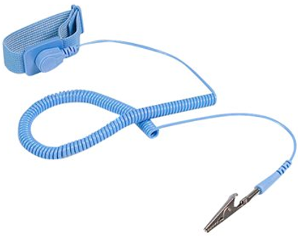
First make sure you work in an ESD safe environment placing the COM board on an anti-static mat. You should also have a wrist strap attached to your wrist and the anti-static mat.
Unfasten screws
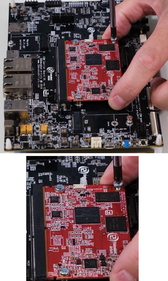
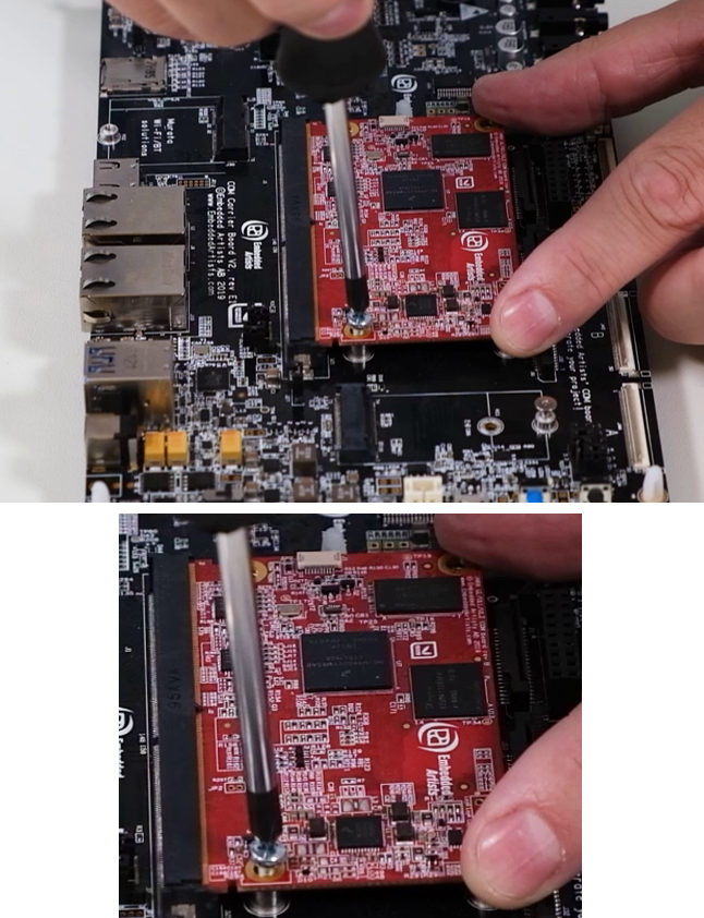
Push down the board in the corners as shown in the figure below while unscrewing. Keep pushing down until all screws have been removed. Begin with the two screws in the corners farthest away from the MXM3 connector. Then move on to the two inner screws.
Remove board
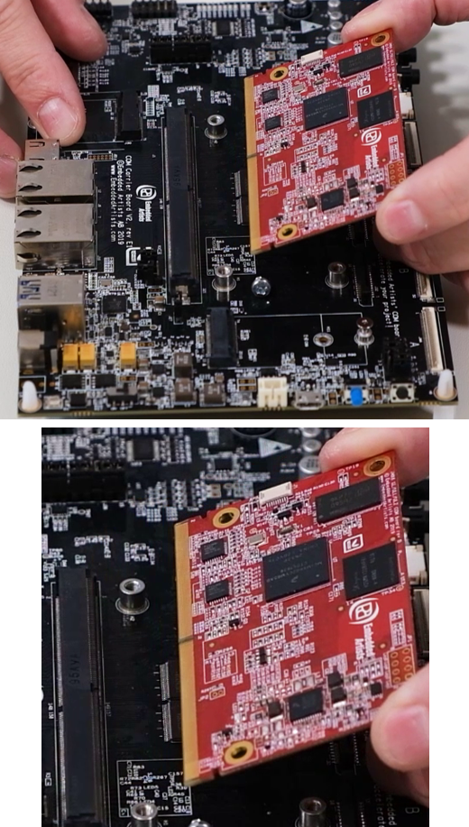
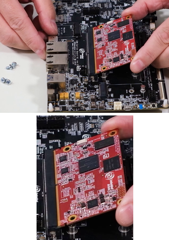
Release the COM board from the MXM3 connector with small movements and pull evenly in both corners as illustrated in the pictures below. When removed, you should put the COM board in an ESD bag or ESD safe environment immediately.
Mount
Inspect gold fingers
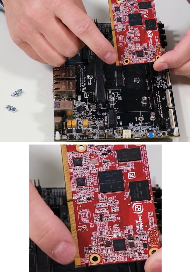
Before you mount the COM board make sure there is no dust on the gold fingers.
Insert COM board
Insert the board in about 45 degrees angle. You will notice the angle that is suitable. Push in the board (with even force in both corners) and make sure it is evenly inserted by looking at the row of gold fingers. When evenly inserted the same area of the gold finger row can be seen in both ends of the MXM3 connector.
Fasten the board
Begin by pushing down the board. Only push in the corners as shown in the figure below and push equally in both corners. Take the first screw and begin with the inner holes. Keep pressing down on the board until both inner screws have been fastened. Don’t tighten the screws fully until all screws have been inserted. Tighten in a cross pattern, but don’t use too much force because it can damage the board.
Be careful with the screwdriver. If it lose the grip on the screw it can easily damage components on the COM board.
Use a heat sink
If you would like to mount a heat sink on the processor, design the heat transfer management system so that the heat sink doesn’t push down on the processor and bend the COM PCB when the heat increases (and materials expand).
Use spring loaded screws, push pins or captive screws when mounting the heat sink in order to get a precise and constant pressure on the processor even if some of the material expand when temperature increase.
Alternatively use a thermal interface material (TIM) that is thicker and designed to absorb material expansion.