Program and access fuses
Introduction
The i.MX processors have One Time Programmable (OTP) fuses which are used to store different kinds of permanent configuration settings. This could, for example, be boot configuration, MAC address, secure boot settings, and so on.
This guide describes how to access and program these fuses from within the U-Boot bootloader and Linux.
Fuses
Organization
On the i.MX processor the fuses are normally organized in several banks where each bank consists of a number of words and each word is typically 32 bits. Each bit can be a one-time-programmable fuse.
As an example, the i.MX7 Dual processor has 16 pieces of 128-bit wide banks with four words in each bank.
Always refer to the User’s Manual for the processor you are using to get the exact description of the fuses on that specific processor.
How to get bank and word index
If you need to determine which bank and word index a specific fuse is located at the easiest is to look at the OCOTP memory map table in the User’s Manual for the processor you are working with.
As an example, look at the figure below and see that OCOTP_LOCK is located at Bank0 Word0
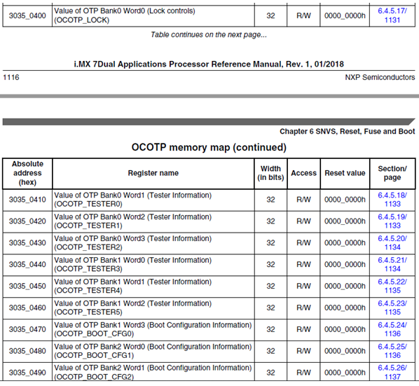
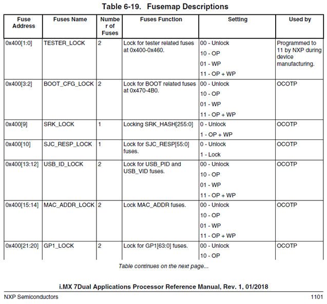
The table in the figure above also specifies the absolute address of the register which for OCOTP_LOCK is 0x30350400. The last part of this address (0x400) is the fuse address usually listed in the Fusemap table in the User’s manual, see figure below.
User's Manual reference: OCOTP memory map
The table below contains the section number in the User’s Manual to the OCOTP memory map for a specific processor. The revision of the manual is given so if you are using a different revision the section number can also be different.
| Processor | Manual revision | Section |
|---|---|---|
| i.MX6 Dual/Quad | Rev 5 | 46.5 |
| i.MX6 SoloX | Rev 3 | 44.5 |
| i.MX6 UltraLite | Rev 2 | 35.5 |
| i.MX7 Dual | Rev 1 | 6.4.5 |
| i.MX8M | Rev 2 | 6.3.5 |
| i.MX8M Mini | Rev 2 | 6.3.4 |
| i.MX8M Nano | Rev 0 | 6.3.4 |
| i.MX7ULP | Rev 0 | 34.7.1.1 |
User's Manual reference: Fusemap Descriptions table
The table below contains the section number in the User’s Manual to the Fusemap Descriptions table for a specific processor. The revision of the manual is given so if you are using a different revision the section number can also be different.
| Processor | Manual revision | Section |
|---|---|---|
| i.MX6 Dual/Quad | Rev 5 | 5.2 |
| i.MX6 SoloX | Rev 3 | 5.3 |
| i.MX6 UltraLite | Rev 2 | 5.3 |
| i.MX7 Dual | Rev 1 | 6.3.3 |
| i.MX8M | Rev 2 | 6.2.3 |
| i.MX8M Mini | Rev 2 | 6.2.3 |
| i.MX8M Nano | Rev 0 | 6.2.3 |
| i.MX7ULP | Rev 0 | Not available at thte time of writing. Must be requested from NXP. |
Examples in Linux
Not all kernel versions support OCOTP access. The recommended way of accessing the OTP fuses are via U-Boot as described in the Examples in U-Boot section.
OCOTP register mapped to sysfs
In Linux it is quite easy to access the fuses since the OCOTP registers are mapped as files in sysfs, more specifically in the directory /sys/fsl_otp. All the files/registers have the prefix HW_OCOTP_ followed by the register name. As an example, the register OCOTP_LOCK described in the How to get bank and word index section has the name HW_OCOTP_LOCK in the file system.
Get value of a register:
cat /sys/fsl_otp/HW_OCOTP_LOCK
0xa0030103
Write fuses in a register:
echo 0x11223344 > HW_OCOTP_YOUR_REGISTER
Double or even triple check the value written to a register because once written it cannot be undone.
Example: iMX7 Dual - Get silicon revision
In the Fusemap description table in the User’s manual (section 6.3.3 in Rev 1 of the manual) it is specified that the silicon revision is available at address 0x440[3:0], that is, bits 0 to 3 at address 0x440. In the OCOTP memory map table (section 6.4.5 in rev 1) absolute address 0x30350440 is called OCOTP_TESTER3 and located at bank 1 word 0.
cat /sys/fsl_otp/HW_OCOTP_TESTER3
0x20000200
Example: iMX6 SoloX - Get speed grading
In the Fusemap description table in the User’s manual (section 5.3 in Rev 3 of the manual) it is specified that speed grading is available at address 0x440[17:16], that is, bits 16 and 17 at address 0x440. In the OCOTP memory map table (section 44.5 in rev 3 manual) absolute address 0x021BC440 is called OCOTP_CFG3 and located at bank 0 word 4.
cat /sys/fsl_otp/HW_OCOTP_CFG3
0x420002
This means that the binary value of bits 16 and 17 is 10b. According to the manual this means that the speed grade is 1000 MHz
Examples in U-Boot
Fuse command
In the U-Boot the fuse command is available that let you read and write fuses. Bank and word index must be specified when accessing the fuses.
Read fuses:
fuse read 0 0
Write fuses (bank and word should be changed to the bank index and word index):
fuse prog bank word 0x11223344
Double or even triple check the value written to a register because once written it cannot be undone.
Example: iMX7 Dual - Get silicon revision
In the Fusemap description table in the User’s manual (section 6.3.3 in Rev 1 of the manual) it is specified that the silicon revision is available at address 0x440[3:0], that is, bits 0 to 3 at address 0x440. In the OCOTP memory map table (section 6.4.5 in rev 1) absolute address 0x30350440 is called OCOTP_TESTER3 and located at bank 1 word 0.
fuse read 1 0
Word 0x00000000: 20000200
Example: iMX6 SoloX - Get speed grading
In the Fusemap description table in the User’s manual (section 5.3 in Rev 3 of the manual) it is specified that speed grading is available at address 0x440[17:16], that is, bits 16 and 17 at address 0x440. In the OCOTP memory map table (section 44.5 in rev 3 manual) absolute address 0x021BC440 is called OCOTP_CFG3 and located at bank 0 word 4.
fuse read 0 4
Word 0x00000004: 00420002
This means that the binary value of bits 16 and 17 is 10b. According to the manual this means that the speed grade is 1000 MHz
Boot from eMMC
An i.MX application processor can boot its software from different boot devices such as eMMC, SD-card, NAND-flash, and so on. Which device to boot from can be selected by for example boot mode pins or by programming fuses. On Embedded Artists COM boards boot mode pins are used by default and these have been setup to use eMMC as boot device.
There can be situations where using boot mode pins can cause problems, for example, if you need to externally drive these pins during reset or if you need to use these pins for other purposes. In this case it is better to program the on-chip OTP fuses for eMMC boot. Please note that you can program the fuses to boot from a different device as well, but the instructions in this section only describe booting from eMMC.
Supported COM boards
Booting from eMMC via fuses is not supported by all COM boards or all revisions of a COM board. The table below lists the COM boards (and from which revision) this feature is supported.
| Board | Revision |
|---|---|
| iMX6 SoloX COM | Rev B2 |
| iMX6 UltraLite COM | Rev B |
| iMX7 Dual COM | Rev B |
| iMX8M Quad COM | All revisions |
| iMX8M Mini uCOM | All revisions |
| iMX8M Nano uCOM | All revisions |
| iMX7ULP uCOM | All revisions |
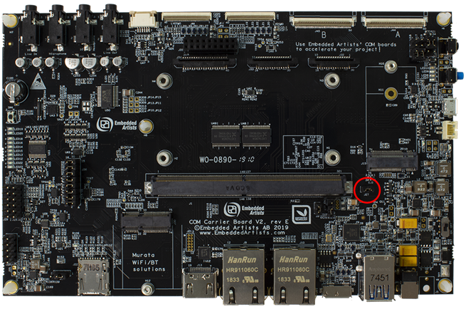
COM Carrier board V2
You can test eMMC booting via fuses using a COM Carrier Board v2, rev E or later. Open (remove) jumper J27, highlighted in the figure below, and you will boot from fuses. Please note that if fuses haven’t been programmed the board will default to USB OTG download (serial download) if J27 is removed.
If you have an older revision of the carrier board you won’t be able to easily test booting via fuses. The reason is that on the older revisions the BOOT_CTRL pin is always grounded.
iMX6 SoloX COM
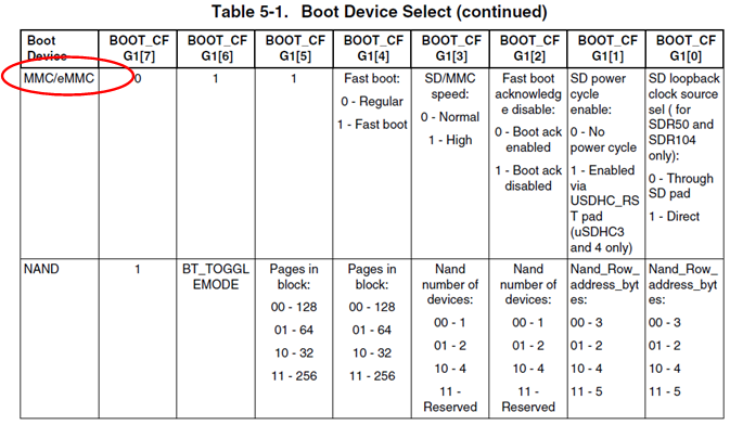
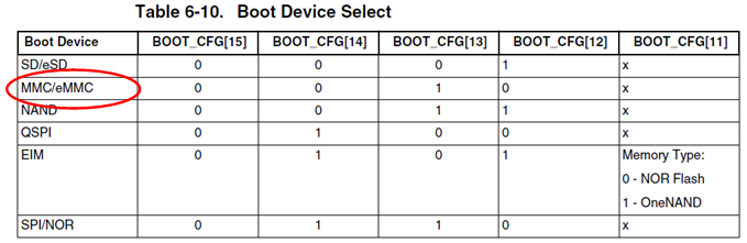
Section 5.1 (Boot Fusemap) in the i.MX6 SoloX User’s Manual contains the table shown in the figure below. In this table you can see that for MMC/eMMC boot BOOT_CFG[6] and BOOT_CFG[5] must be set to 1 while BOOT_CFG[7] must be 0.
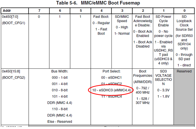
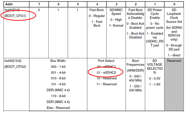
There is a more detailed fusemap table specifically for MMC/eMMC booting, see the figure below. For the iMX6 SoloX COM board the eMMC is on the eSDHC3 interface. This means that Port Select must be set to 10, that is, bit 12 must be set to 1.
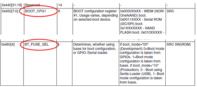
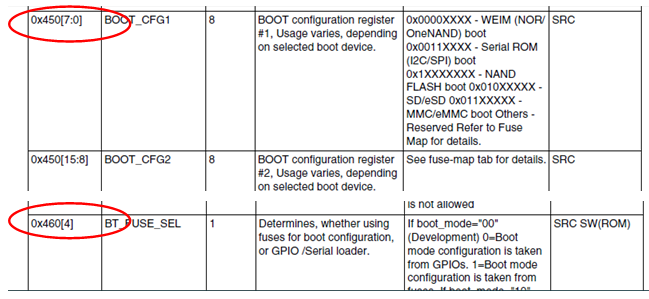
The Fuse Description Table from section 5.3 in the i.MX6 SoloX User’s Manual gives that BOOT_CFG is at fuse address 0x450, see the figure below. We also need to know the address of the BT_FUSE_SE fuse since this must be set to boot from fuses. This fuse is available at address 0x460.
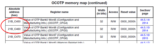
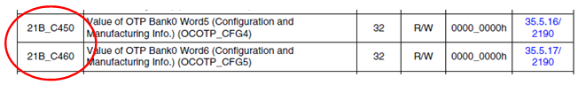
As described in the How to get bank and word index section we can now use the OCOTP Memory Map to find which OTP bank and word the fuse address 0x450 and 0x460 is mapped to. As shown in the figure below this is Bank0 Word5 and Bank0 Word6.
With this information we can now determine that bank0 and word5 should be programmed with a value where bit 5, bit 6 and bit 12 (BOOT_CFG) are set to 1. The hexadecimal value that corresponds to these bits being set to 1 is 0x00001060.
For bank0 word6, bit 4 (BT_FUSE_SEL) should be set to 1. The hexadecimal value is 0x00000010.
Instructions
From the U-Boot console run the following commands to program the fuses:
These commands cannot be undone.
fuse prog 0 5 00001060
fuse prog 0 6 00000010
iMX6 UltraLite COM
Section 5.1 (Boot Fusemap) in the i.MX6 UltraLite User’s Manual contains the table shown in the figure below. In this table you can see that for MMC/eMMC boot, BOOT_CFG[6] and BOOT_CFG[5] must be set to 1 while BOOT_CFG[7] must be 0.
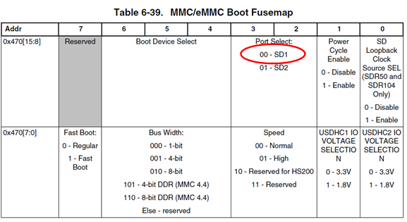
There is a more detailed fusemap table specifically for MMC/eMMC booting, see the figure below. For the iMX6 UltraLite COM board the eMMC is on the eSDHC2 interface. This means that Port Select must be set to 01, that is, bit 11 must be set to 1.
The Fuse Description Table from section 5.3 in the i.MX6 UltraLite User’s Manual gives that BOOT_CFG is at fuse address 0x450, see the figure below. We also need to know the address of the BT_FUSE_SEL fuse since this must be set to boot from fuses. This fuse is available at address 0x460.
As described in the How to get bank and word index section we can now use the OCOTP Memory Map to find which OTP bank and word the fuse address 0x450 and 0x460 is mapped to. As shown in the figure below this is Bank0 Word5 and Bank0 Word6.
With this information we can now determine that bank0 and word5 should be programmed with a value where bit 5, bit 6 and bit 11 (BOOT_CFG) are set to 1. The hexadecimal value that corresponds to these bits being set to 1 is 0x00000860.
For bank0 word6, bit 4 (BT_FUSE_SEL) should be set to 1. The hexadecimal value is 0x00000010.
Instructions
From the U-Boot console run the following commands to program the fuses:
These commands cannot be undone.
fuse prog 0 5 00000860
fuse prog 0 6 00000010
iMX7 Dual COM
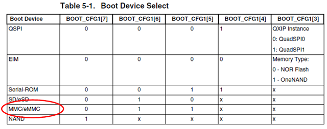
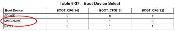
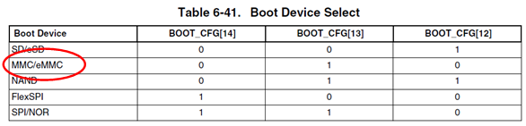
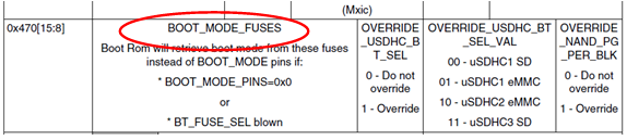
Section 6.3.1 (Boot Fusemap) in the i.MX7 Dual User’s Manual contains the table shown in the figure below. In this table you can see that for MMC/eMMC boot, BOOT_CFG[13] must be set to 1 while BOOT_CFG[12], BOOT_CFG[14], and BOOT_CFG[15] must be 0.
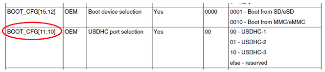
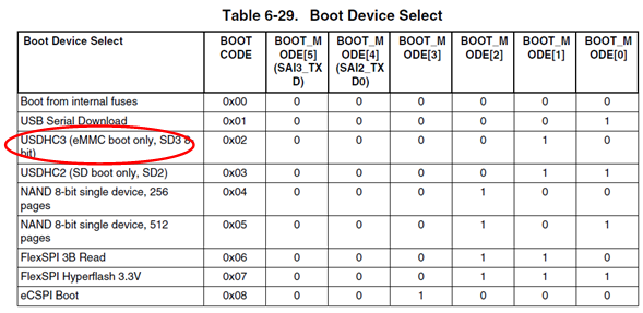
For iMX7 Dual COM board, eMMC is attached to the USDHC3 interface. Fuses must be programmed to select the correct USDHC port. This is described in section 6.6.5.3.1 – Expansion device eFUSE configuration – in the User’s Manual for the i.MX7 Dual processor, see the figure below. BOOT_CFG[11:10] must be set to 10 to choose USDHC-3.
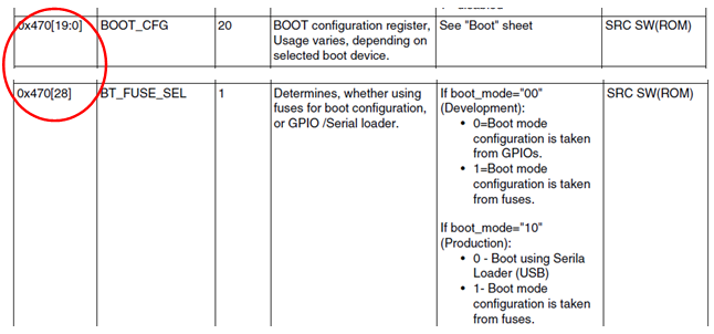
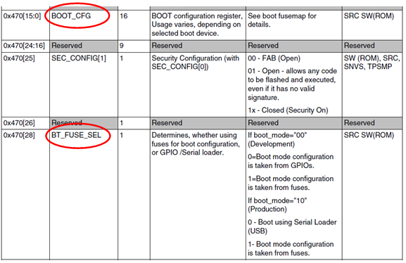
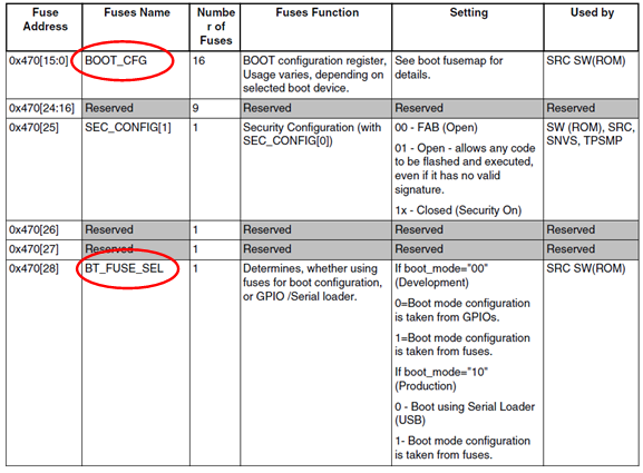
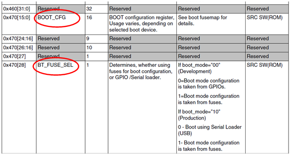
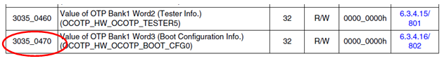
The Fuse Description Table from section 6.3.3 in the i.MX7 Dual User’s Manual gives that BOOT_CFG is at fuse address 0x470, see the figure below. We also need to know the address of the BT_FUSE_SEL fuse since this must be set to boot from fuses. This fuse is also available at address 0x470.
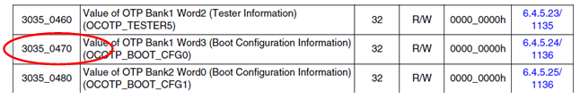
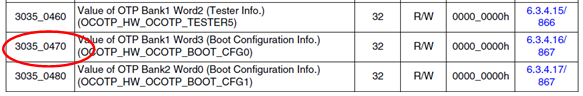
As described in the How to get bank and word index section we can now use the OCOTP Memory Map to find which OTP bank and word the fuse address 0x470 is mapped to. As shown in Figure 15 below this is Bank1 Word3.
With this information we can now determine that bank1 and word3 should be programmed with a value where bit 11 (port selection), bit 13 (device selection) and bit 28 (BT_FUSE_SEL) are set to 1. The hexadecimal value that corresponds to these bits being set to 1 is 0x10002800.
Instructions
From the U-Boot console run the following commands to program the fuses:
These commands cannot be undone.
fuse prog 1 3 10002800
iMX8M Quad COM
Section 6.2.1 (Boot Fusemap) in the i.MX8 M User’s Manual contains the table shown in the figure below. In this table you can see that for MMC/eMMC boot, BOOT_CFG[13] must be set to 1 while both BOOT_CFG[12] and BOOT_CFG[14] must be 0.
There is a more detailed fusemap table specifically for MMC/eMMC booting, see the figure below. For the iMX8M Quad COM board the eMMC is on the SD1 interface. This means that Port Select must be set to 00 which is the default value so there is no need to change these fuse bits.
The Fuse Description Table from section 6.2.3 in the i.MX8 M User’s Manual gives that BOOT_CFG is at fuse address 0x470, see the figure below. We also need to know the address of the BT_FUSE_SEL fuse since this must be set to boot from fuses.
As described in the How to get bank and word index section we can now use the OCOTP Memory Map to find which OTP bank and word the fuse address 0x470 is mapped to. As shown in the figure below this is Bank1 and Word3.

With this information we can now determine that bank1 and word3 should be programmed with a value where bit 13 (BOOT_CFG[13]) and bit 28 (BT_FUSE_SEL) are set to 1. The hexadecimal value that corresponds to these two bits being set to 1 is 0x10002000.
Instructions
From the U-Boot console run the following commands to program the fuses:
These commands cannot be undone.
fuse prog 1 3 10002000
iMX8M Mini uCOM
Section 6.2.1 (Boot Fusemap) in the i.MX8 M Mini User’s Manual contains the table shown in the figure below. In this table you can see that for MMC/eMMC boot, BOOT_CFG[13] must be set to 1 while both BOOT_CFG[12] and BOOT_CFG[14] should be 0.
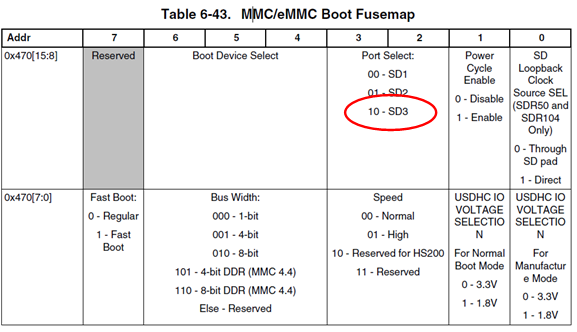
There is a more detailed fusemap table specifically for MMC/eMMC booting, see Figure 21. For the iMX8M Mini uCOM board the eMMC is on the SD3 (usdhc3) interface. This means that Port Select must be set to 10, that is, bit 11 must be set to 1.
The Fuse Description Table from section 6.2.3 in the i.MX8 M Mini User’s Manual gives that BOOT_CFG is at fuse address 0x470, see the figure below. We also need to know the address of the BT_FUSE_SEL fuse since this must be set to boot from fuses.
As described in the How to get bank and word index section we can now use the OCOTP Memory Map to find which OTP bank and word the fuse address 0x470 is mapped to. As shown in the figure below this is Bank1 Word3.
With this information we can now determine that bank1 and word3 should be programmed with a value where bit 11 (BOOT_CFG[11] - Port Select), bit 13 (BOOT_CFG[13]) and bit 28 (BT_FUSE_SEL) are set to 1. The hexadecimal value that corresponds to these two bits being set to 1 is 0x10002800.
Instructions
From the U-Boot console run the following commands to program the fuses:
These commands cannot be undone.
fuse prog 1 3 10002800
iMX8M Nano uCOM
Section 6.2.1 (Boot Fusemap) of the i.MX8 M Nano User’s Manual contains the table shown in the figure below. In this table you can see that for USDHC3 (eMMC) boot code should be set to 0x02, that is, BOOT_MODE[1] should be 1.
The Boot fusemap shows that the boot mode fuses are located at bits 12-15 (BOOT_MODE[0] is on bit 12, BOOT_MODE[1] on bit 13, and so on), see the figure below.
The Fuse Description Table from section 6.2.3 in the i.MX8 M Nano User’s Manual gives that BOOT_CFG is at fuse address 0x470, see the figure below. We also need to know the address of the BT_FUSE_SEL fuse since this must be set to boot from fuses.
As described in the How to get bank and word index section we can now use the OCOTP Memory Map to find which OTP bank and word the fuse address 0x470 is mapped to. As shown in the figure below this is Bank1 Word3
With this information we can now determine that bank1 and word3 should be programmed with a value where bit 13 (BOOT_MODE[1]), and bit 28 (BT_FUSE_SEL) are set to 1. The hexadecimal value that corresponds to these two bits being set to 1 is 0x10002000.
Instructions
From the U-Boot console run the following commands to program the fuses:
These commands cannot be undone.
fuse prog 1 3 10002000
iMX7ULP uCOM
For the iMX7ULP the Fusemap is not published in the User’s Manual. Instead you need to request this from NXP. Because of this, there are no figures/screenshots included in this section for the fusemap. It is only described which OTP fuses you need to program.
The boot device selection is controlled via BT0_CFG1 which is located at Bank2 Word 4.
The BT_FUSE_SEL must also be set and this fuse is located at Bank2 Word7.
Instructions
From the U-Boot console run the following commands to program the fuses:
These commands cannot be undone.
fuse prog 2 4 00400002
fuse prog 2 7 00008000
Program Fuses from UUU
UUU (Universal Update Utility) is used to program the boards with new images / software. You can download zip files containing the UUU utility and configuration files from https://sw.embeddedartists.com.
In short, UUU is a utility program used in combination with one or more configuration files. The configuration files contain the instructions to run when updating the board. If needed, you can program fuses from such a configuration file.
Below is an example from the configuration file bootloader.uuu belonging to the iMX8M Mini uCOM board. Here we have added the highlighted command (it is not normally included) below which will enable eMMC boot on the iMX8M Mini uCOM board. Please note the -y that is added so you don’t need to confirm the command.
Do not just copy the line below to your configuration file. Double-check the fuses you want to program before adding such a command. Once fuses have been programmed it cannot be undone.
...
FB: ucmd mmc dev ${emmc_dev}
FB: ucmd mmc info
FB: ucmd fuse prog -y 1 3 10002800
FB: flash bootloader files/imx-boot-imx8mmea-ucom-sd.bin
FB: done