Device tree
Introduction
The device tree is a data structure used for describing hardware. Take a Computer-on-Module (COM) such as the iMX8M Mini uCOM board as an example. It consists of several hardware devices (peripherals) such as i.MX 8M Mini application processor, LPDDR4 memory, eMMC flash, Ethernet PHY, and Power Management IC (PMIC), see the figure below for a block diagram.
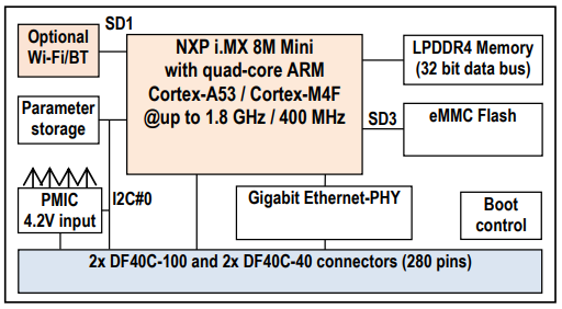
The iMX8M Mini uCOM board is then used in combination with a carrier board such as the COM Carrier board v2 used in a Developer’s Kit. This carrier board adds more peripherals and especially interfaces such as UART, USB, PCIe, SD card, audio codec, and more. To be even more specific the i.MX 8M application processor in itself also contains several peripherals such as I2C, SPI, PCIe, MIPIDSI, memory buses, and more.
To be able to use a hardware device within an operating system, (we will use Linux kernel as example), a device driver is needed. The driver needs to be initialized to work with the specific hardware / board configuration. This could for example be a device address (if attached to a bus), pin configuration, clock to assign to the device, and so on.
Before device trees, the Linux kernel often contained the board specific code, such as the address of the device. This meant that the kernel had to be re-compiled when something hardware specific had to be changed. Take the PMIC as an example. This device is attached to the I2C bus at a specific I2C address (0x4B) and if the address had to be changed a new kernel had to be compiled. Another, but related problem, is if you offer different configurations of your product. In this case you had to provide different Linux kernels for each configuration in the case when the kernel contained board specific code.
The device tree solves these problems by moving board / device specific code out of the kernel and into the device tree file. This file can then be maintained and compiled separate from the kernel which will make the kernel more portable across different boards. In the example of using the Linux kernel the device tree will typically be loaded by the U-Boot bootloader.
It is important to note that a device tree won’t be needed for discoverable devices such as devices attached to a USB bus. The USB protocol has been designed to be able to detect if a device is attached and then probe that device for information that is given to the device driver.
Data structure format
The data structure can be seen as a tree structure with nodes and properties. Each node (except the root node) has one parent in the tree. A node contains a list of properties, which are key-value pairs, and can also contain child nodes. This kind of structure makes it quite easy for a human to read and understand how the hardware is organized.
The latest device tree specification can be found at https://www.devicetree.org/specifications/.
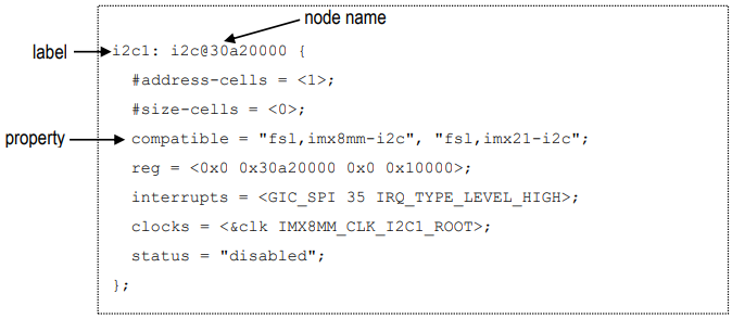
The figure below shows an example of a node that describes an I2C bus. In this example the node has been assigned a label (i2c1). This label can be used to reference the node from other parts of the device tree (instead of referencing the node name). The node name must be unique and should describe the general class of the device. In the example below the node name (i2c@30a20000) consists of a name (i2c) followed by a unit-address (@30a20000). The unit-address is omitted if there is no address associated with the device. In the example below you can see that the unit-address is also specified in the reg property.
One important property is the status property. Below you can see that it is set to disabled which means that the device won't be activated in the kernel.
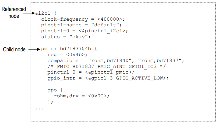
The figure below shows an example where the i2c1 node is referenced and properties added and changed. The status property is for example set to okay meaning that the I2C1 bus is activated. A child node (pmic) is added to the node since the actual PMIC device is attached to the I2C1 bus on the iMX8M Mini uCOM board. For the PMIC device you can see that the I2C address is 0x4b (both set in the unit address field and the reg property).
Property values
As previously mentioned, properties consist of key-value pairs and the key (the property name) is a string of 1 to 31 characters. The value can however be of different types.
- Empty value. This indicates a true / false property and only contains the property name.
enable-active-high;
- String value.
status = "okay";
- String list. Strings are separated with comma (‘,’).
compatible = "rohm,bd71840", "rohm,bd71837";
- Cell property array. The format is specific to the property. Below are two examples where the
regproperty contains one hexadecimal integer value, while thegpio_intrproperty contains one reference to another node and two integer values.reg = <0x4b>;gpio_intr = <&gpio1 3 GPIO_ACTIVE_LOW>;
- Binary data. The data is delimited with square brackets.
local-mac-address = [00 1A F1 01 04 15];
Aliases
There is a special node in the device tree called aliases. This node can be used to assign a short alias to a full node path. This alias can then be used within the Linux kernel or U-Boot when accessing a node instead of using the full path to the node. Aliases are not used within the device tree source (.dts) to reference a node. Instead, labels are used within the device tree source.
The example below, which is from imx8mm.dtsi can look quite confusing since for example the alias i2c0 reference i2c1. The right-hand side is however in this case a label and means that the alias i2c0 will have the value /i2c@30a20000, i.e., the full path to the I2C node.
   aliases {
         ethernet0 = &fec1;
         i2c0 = &i2c1;
         i2c1 = &i2c2;
         i2c2 = &i2c3;
         i2c3 = &i2c4;
         serial0 = &uart1;
The complete alias section for the iMX8M Mini uCOM can be seen by following the link below.
Source files and compiler
There are two types of source files used for device trees.
.dtsi– includable device tree file. This file is not considered a standalone device tree, but instead it is included in either another.dtsifile or in a .dts file that will complete the device tree. These types of files are typically used when describing the application processor, such asfsl-imx8mm.dtsifor the i.MX 8M Mini application processor..dts– This is a standalone device tree that can be compiled into a binary file (.dtb). Please note that a.dtsfile can include another.dtsfile. The file to include doesn't have to be a.dtsi. file.
A device tree source file is compiled into a binary device tree (.dtb) by using the device tree compiler (dtc). Most often you won't use this compiler directly, but instead build the .dtb files within the Linux kernel. In this case you will use the dtbs target.
make dtbs
Linux
Within the Linux kernel the device tree files are available under the arch directory. The exact location depends on which target you are using. Note that the iMX93 was introduced in version 6.1.
32-bit CPUs - iMX6 and iMX7 - use arch/arm/boot/dts/
https://github.com/embeddedartists/linux-imx/tree/ea_5.15.y/arch/arm/boot/dts
64-bit CPUs - iMX8 and iMX93 - use arch/arm64/boot/dts/freescale/
https://github.com/embeddedartists/linux-imx/tree/ea_6.1.y/arch/arm64/boot/dts/freescale
U-Boot
Within the U-Boot bootloader the device tree files are available under the arch/dts directory. Below you can see the exact location (for version 2018.03).
https://github.com/embeddedartists/uboot-imx/tree/ea_v2018.03/arch/arm/dts
Pin muxing
A pin on an i.MX application processor may have more than one function, that is, it can be connected to more than one internal peripheral (but only one at a time). The selection of pin function is handled by an input-output multiplexer usually called IOMUX. Besides selecting which function to use the multiplexer is also used to configure other characteristics such as drive strength, hysteresis, open drain, pull-up/pull-down, and so on.
Pin muxing is handled in the device tree in a node called iomuxc. In this node you configure a pin within a child node that must contain the property fsl,pins with a value consisting of several cells.
If we take the I2C node from the Data structure format section as example you can see that it has a property called pinctrl- that has a reference to a node called pinctrl_i2c1. The node pinctrl_i2c1 is a child node to iomuxc.
pinctrl-0 = <&pinctrl_i2c1>;
Below is the pinctrl_i2c1 node with the fsl,pins property and a list of two pins being configured. The first part of a row is a pre-processor macro that will be expanded to several cells. For the i.MX 8M Mini this macro is defined in arch/arm64/boot/dts/freescale/imx8mm-pinfunc.h (up to version 4.14.98 it was include/dt-bindings/pinctrl/pins-imx8mm.h). For i.MX6 and i.MX7 corresponding files are located in arch/arm/boot/dts. In general, you don’t need to know the exact values set in the macro, but only how to interpret the name of the macro since a specific naming convention is being used.
The name consists of three parts.
MX8MM_IOMUX: A prefix which should be unique and usually identifies the processor.I2C1_SCL: The pad name (in the NXP manual it is usually referred to as a pad instead of a pin) on the processor which normally is the same as the main function of the pad.I2C1_SCL: The function the pad should get. In this example this is the same as the pad name, but if you look inpins-imx8mm.hyou can see that it could have been set to for exampleGPIO5_IO14if you wanted it to be configured to be a GPIO.
pinctrl_i2c1: i2c1grp {
  fsl,pins = <
    MX8MM_IOMUXC_I2C1_SCL_I2C1_SCL   0x400001c3
    MX8MM_IOMUXC_I2C1_SDA_I2C1_SDA   0x400001c3
  >;
};
The second part of a row is a hexadecimal value that sets the pad control registers – the characteristics of the pad. The user’s manual for the processor must be consulted to interpret this value. If we continue with the I2C example for the i.MX 8M Mini processor and look in the manual (Rev 2 was used when writing this document) we can find a description of the control register in section 8.2.5.283 – Pad Control Register (IOMUXC_SW_PAD_CTL_PAD_I2C1_SCL).
The table from that section is replicated below and a third column has been added with a description of the specific value used for the I2C1_SCL pad.
| Field | Description | I2C1_SCL value |
|---|---|---|
| 31-0 - | This field is reserved | - |
| 8 PE | Pull resistors enable field 0 = Disable pull resistors 1 = Enable pull resistors | 1 = Enable pull resistors |
| 7 HYS | Hysteresis enable field 0 = Select CMOS input 1 = Select Schmitt input | 1 = Schmitt input |
| 6 PUE | 0 = Select pull-down resistors 1 = Select pull-up resistors | 1 = Pull-up resistors enabled |
| 5 ODE | Open drain enable field 0 = Disable open drain mode 1 = Enable open drain mode | 0 = Open drain disabled |
| 4-3 FSEL | Slew rate field (lsb field not used hence the X below) 0X – Select slow slew rate (SR=1) 1X – Select fast slew rate (SR=0) | 00 = Slow slew rate |
| 2-0 | Drive strength field (lsb field not used hence the X below) 00X – Drive strength X1 10X – Drive strength X2 01X – Drive strength X4 11X – Drive strength X6 | 011 = Drive strength X4 |
Modify device tree from U-Boot
The U-Boot is responsible for loading the device tree and providing it to the Linux kernel. The U-Boot also has the fdt command that can be used to parse and modify the device tree before it is provided to Linux. By using the fdt command, you can make temporary changes to the device tree without having to modify and re-compile the .dts file.
Usage
From within the U-Boot console run the command below to get a description of which fdt commands that are available.
help fdt
Usage:
fdt addr [-c] <addr> [<length>]   - Set the [control] fdt location to <addr>
fdt boardsetup                    - Do board-specific set up
fdt systemsetup                   - Do system-specific set up
fdt move <fdt> <newaddr> <length> - Copy the fdt to <addr> and make it active
...
The commands that you will most often use are print, set, rm and possibly mknod.
Test different commands
This section describes how you can test some of the fdt commands.
Load the device tree
The device tree must be loaded before you can modify it. Do this by setting skip_booting and then running boot.
setenv skip_booting yes
boot
switch to partitions #0, OK
mmc1(part 0) is current device
1492 bytes read in 7 ms (208 KiB/s)
Running bootscript from mmc ...
## Executing script at 40480000
39658 bytes read in 9 ms (4.2 MiB/s)
!!!! Selected to skip booting !!!!
!!!! Unset skip_booting variable to enable booting again !!!!
Print the device tree
When the device tree has been loaded you can inspect it by using fdt print. You enter a path to the part of the tree you want to print. If you want to see the entire tree you print the root (‘/’). You can also use fdt list if you just want to print one level of nodes, for example, all children just beneath the root, but not any of the child nodes children.
Since the device tree is usually quite large it is better to only print the part you are interested in. You need to specify the complete path to the node or if an alias exist use that alias. If we take the I2C node described in the Data structure format section and list its content it looks like below. The I2C node is available directly under the root node.
fdt list /i2c@30a20000
i2c@30a20000 {
        #address-cells = <0x00000001>;
        #size-cells = <0x00000000>;
        compatible = "fsl,imx8mm-i2c", "fsl,imx21-i2c";
        reg = <0x00000000 0x30a20000 0x00000000 0x00010000>;
        interrupts = <0x00000000 0x00000023 0x00000004>;
        clocks = <0x00000004 0x000000a4>;
        status = "okay";
        clock-frequency = <0x00061a80>;
        pinctrl-names = "default";
        pinctrl-0 = <0x0000001b>;
        bd71837@4b {
        };
        at24@55 {
        };
        wm8731@1a {
        };
};
You can get the same result by using the alias i2c0. See the Aliases section for information about aliases.
fdt list i2c0
Change the value of a property
Use fdt set to change the value of a property. In this example we will deactivate the audio codec (wm8731) which we could see as a child node to i2c@30a20000 in the example above.
fdt set /i2c@30a20000/wm8731 status "disabled"
Boot Linux with the modified device tree
If you want to test the modifications you have done you cannot run just boot since this would mean that the device tree would be re-loaded. Instead you need to run some of the individual commands part of the boot process. In most cases this involves loading the image, setting the mmc arguments and then issuing the boot command. Which boot command to use can differ (booti or bootz) for different boards, but you can find it by inspecting the bootcmd variable. For the iMX8M Mini uCOM it looks like below.
run loadimage
run mmcargs
booti ${loadaddr} - ${fdt_addr}
Add to cmd_custom
If you want the modification of the device tree to be more permanent, that is, it should be done for consecutive boots without having to manually enter the fdt commands, you can add the changes to the cmd_custom variable.
setenv cmd_custom fdt set /i2c@30a20000/wm8731 status "disabled"
saveenv
If you need to run several fdt commands you can separate them with a semicolon (';'). Don't forget to escape ('') the semicolon otherwise it will be interpreted incorrectly by the U-Boot. As an example, to disable both the wm8731 codec and the eeprom:
setenv cmd_custom fdt set /i2c@30a20000/wm8731 status "disabled" \; fdt set /i2c@30a20000/at24@55 status "disabled"
saveenv
Tools
The sections below have been flagged with TARGET and/or HOST to show where the command is typically used.
DTC (TARGET and HOST)
The Device Tree Compiler, dtc, is used under the hood when compiling the device tree source files using the make dtbs
command. It can however also be used standalone to compile or decompile single files.
The dtc command is not included in the ea-image-base yocto image, but it can be added by including "IMAGE_INSTALL:append += "dtc" in conf/local.conf.
To decompile a dtb file (either on target or on the host computer):
dtc -I dtb -O dts -o my_decompiled.dts imx8mm-ea-ucom-kit_v3.dtb
The my_decompiled.dts file can then be modified and then compiled back into a dtb file with
dtc -I dts -O dtb -o imx8mm-ea-ucom-kit_v3.dtb my_decompiled.dts
dtx_diff (HOST)
The dtx_diff is a script that, among other things, compares two dtb files without you having to decompile them to dts first.
The dtx_diff script is available in the scripts/dtc folder.
One example, comparing the compiled version of imx8mm-ea-ucom-kit_v3.dts to imx8mm-ea-ucom-kit_v3-pcie.dts
./scripts/dtc/dtx_diff arch/arm64/boot/dts/freescale/imx8mm-ea-ucom-kit_v3{,-pcie}.dtb
--- arch/arm64/boot/dts/freescale/imx8mm-ea-ucom-kit_v3.dtb
+++ arch/arm64/boot/dts/freescale/imx8mm-ea-ucom-kit_v3-pcie.dtb
@@ -329,7 +329,7 @@
                        phandle = <0x2f>;
                        post-power-on-delay-ms = <0x78>;
                        reset-gpios = <0x4f 0x01 0x01>;
-                       status = "okay";
+                       status = "disabled";
                };
        };

@@ -1307,7 +1307,7 @@
                                pinctrl-names = "default\0state_100mhz\0state_200mhz";
                                pm-ignore-notify;
                                reg = <0x30b40000 0x10000>;
-                               status = "okay";
+                               status = "disabled";

                                bcrmf@1 {
                                        compatible = "brcm,bcm4329-fmac";
@@ -1590,7 +1590,7 @@
                                reg = <0x32f00000 0x10000>;
                                reset-names = "pciephy";
                                resets = <0x1c 0x1a>;
-                               status = "disabled";
+                               status = "okay";
                        };

                        usb@32e40000 {
@@ -1722,7 +1722,7 @@
                        reset-gpio = <0x4f 0x07 0x01>;
                        reset-names = "apps\0turnoff";
                        resets = <0x1c 0x1c 0x1c 0x1d>;
-                       status = "disabled";
+                       status = "okay";
                        vpcie-supply = <0x50>;
                };
/proc/device-tree (TARGET)
Sometime it is helpful to check the value of some dtb entry, for debugging, or checking that your dtb really got updated after you modfified, etc. An alternative to decompiling the dtb file is to check values using the entries in /proc/device-tree.
# ls /proc/device-tree/
'#address-cells'   clock-ext1      compatible         model        reserved-memory
'#size-cells'      clock-ext2      cpus               name         serial-number
 aliases           clock-ext3      gasket@32e28060    opp-table    soc@0
 busfreq           clock-ext4      gpu@38000000       pmu          thermal-zones
 camera            clock-osc-24m   interrupt-parent   psci         timer
 chosen            clock-osc-32k   memory@40000000    regulators   usbphynop1
# ls /proc/device-tree/aliases/
csi0       gpio0  gpio2  gpio4  i2c1  i2c3  mmc0  mmc2  serial0  serial2  spi0  spi2
ethernet0  gpio1  gpio3  i2c0   i2c2  isi0  mmc1  name  serial1  serial3  spi1
# ls /proc/device-tree/aliases/i2c
i2c0  i2c1  i2c2  i2c3
# cat /proc/device-tree/aliases/i2c1
/soc@0/bus@30800000/i2c@30a30000
# ls /proc/device-tree/soc\@0/bus\@30800000/i2c\@30a30000/
'#address-cells'   clock-frequency   compatible   name         pinctrl-0       reg
'#size-cells'      clocks            interrupts   pca6416@21   pinctrl-names   status
# ls /proc/device-tree/soc\@0/bus\@30800000/i2c\@30a30000/pca6416\@21/
'#gpio-cells'   compatible   gpio-controller   gpio-line-names   name   phandle   reggpio0
dt_to_config (HOST)
The dt_to_config is a script to help find which Linux kernel configuration flags and drivers correspond to a node in the device tree. This is a part of the script's own documentation:
This program uses heuristics to guess which driver(s) support each compatible string and which config option(s) enables the driver(s). Do not believe that the reported information is fully correct. This program is intended to aid the process of determining the proper kernel configuration for a device tree, but this is not a fully automated process -- human involvement may still be required!
The driver match heuristic used is to search for source files containing the compatible string enclosed in quotes.
This program might not be able to find all drivers matching a compatible string.
The dt_to_config script is available in the scripts/dtc folder.
The script should be run from the root directory of the Linux kernel source tree.
One example where the current configuration (the .config file) when parsing the imx8mm-ea-ucom-kit_v3.dts:
Here we want information about the imx8mm-ea-ucom-kit_v3.dts file:
# cd ~/gits/linux-imx
# ./scripts/dtc/dt_to_config arch/arm64/boot/dts/freescale/imx8mm-ea-ucom-kit_v3.dts

...
-d-c--------- : /soc@0/bus@30800000/i2c@30a20000/bd71847@4b : rohm,bd71847 : drivers/mfd/rohm-bd718x7.c : CONFIG_MFD_ROHM_BD718XX : none
-d-c--------- : /soc@0/bus@30800000/i2c@30a20000/pca9530@61 : nxp,pca9530 : drivers/leds/leds-pca9532.c : CONFIG_LEDS_PCA9532 : none
...
The output above shows only two lines but in reality several pages of information is produced. The two lines
that have been singled out above shows the I2C nodes (bd71847@4b and pca9530@61), their respective
compatible strings "rohm,bd71847" and "nxp,pca9530", the driver files and the CONFIG_ flags.
If you have configured your kernel (e.g. by running make ea_imx8_defconfig) and you pass that .config file
as an argument to dt_to_config, then you will get a bit more information - the end of the line shows the
value of the configuration flag instead of none:
# cd ~/gits/linux-imx
# ./scripts/dtc/dt_to_config -c .config arch/arm64/boot/dts/freescale/imx8mm-ea-ucom-kit_v3.dts

...
-d-c-------y- : /soc@0/bus@30800000/i2c@30a20000/bd71847@4b : rohm,bd71847 : drivers/mfd/rohm-bd718x7.c : CONFIG_MFD_ROHM_BD718XX : y
-d-c------m-F : /soc@0/bus@30800000/i2c@30a20000/pca9530@61 : nxp,pca9530 : drivers/leds/leds-pca9532.c : CONFIG_LEDS_PCA9532 : m
...
/sys/kernel/debug/pinctrl/pinctrl-handles (TARGET)
The debug file system /sys/kernel/debug has some information about the pinmux configuration in use.
The information is available in the /sys/kernel/debug/pinctrl/pinctrl-handles file.
# cat /sys/kernel/debug/pinctrl/pinctrl-handles
Requested pin control handlers their pinmux maps:
device: 30860000.serial current state: default
  state: default
    type: MUX_GROUP controller 30330000.pinctrl group: uart1grp (10) function: imx8mmea-ucom-kit (1)
    type: CONFIGS_PIN controller 30330000.pinctrl pin MX8MM_IOMUXC_UART1_RXD (141)config 00000140
    type: CONFIGS_PIN controller 30330000.pinctrl pin MX8MM_IOMUXC_UART1_TXD (142)config 00000140
    type: CONFIGS_PIN controller 30330000.pinctrl pin MX8MM_IOMUXC_UART3_RXD (145)config 00000140
    type: CONFIGS_PIN controller 30330000.pinctrl pin MX8MM_IOMUXC_UART3_TXD (146)config 00000140
...
The command prints a lot of information, the selected lines above corresponds to this fragment of the imx8mm-ea-ucom-kit_v3.dts:
pinctrl_uart1: uart1grp {
	fsl,pins = <
		MX8MM_IOMUXC_UART1_RXD_UART1_DCE_RX	0x140
		MX8MM_IOMUXC_UART1_TXD_UART1_DCE_TX	0x140
		MX8MM_IOMUXC_UART3_RXD_UART1_DCE_CTS_B	0x140
		MX8MM_IOMUXC_UART3_TXD_UART1_DCE_RTS_B	0x140
	>;
};
Frequently asked questions
Do I need to create my own device tree file?
If you are developing your own product by using one of Embedded Artists COM boards you will most likely need to develop your own carrier board. Your carrier board will contain the specific peripherals and interfaces needed by your product. This mean that you have to use your own .dts file that defines the peripherals you are using.
How do I create my own device tree file?
The recommendation is that you start with one of the files (there can be more than one) that has been created for the Embedded Artists Developer's Kit you are using, for example, fsl-imx8mm-ea-ucom-kit_v2.dts if you are using iMX8M Mini uCOM.
-
Copy our .dts file and give it a new name for your product.
-
Modify your file so it matches your hardware. This usually involves removing nodes that you don't need, but also adding new nodes for peripherals that are new and specific to your hardware.
-
Add the new .dts file to the Makefile so that it will be built. Below is a link to the Makefile used for fsl-imx8mm-ea-ucom-kit_v2.dts.
-
The U-Boot environment has a variable named fdt_file that defines which .dtb file to load. You have to either update this variable dynamically using setenv or change the default setting in the U-Boot source code.
-
Change dynamically in U-Boot environment
setenv fdt_file fsl-imx8mm-my_device.dtb
saveenv -
Change default values statically in U-Boot source. The link below shows where and how it is configured for iMX8M Mini uCOM. It is done in a similar way for the other COM boards.
https://github.com/embeddedartists/uboot-imx/blob/ea_v2018.03/include/configs/mx8mmea-ucom.h#L166
-
-
If you want your new file to be included in a Yocto image you must update the machine file. The link below goes to the machine file for the iMX8M Mini uCOM board. It is similar for the other COM boards.
https://github.com/embeddedartists/meta-ea/blob/ea-4.14.98/conf/machine/imx8mmea-ucom.conf#L22
- If you want the new file to be copied to the target when running the UUU tool you must update the uuu scripts (can be downloaded from https://sw.embeddedartists.com). The example below is from the full_tar.uuu file for the iMX8M Mini uCOM board.
# Copy kernel and dtb files
FBK: ucp files/Image-imx8mmea-ucom.bin t:/mnt/fat/Image
FBK: ucp files/fsl-imx8mm-ea-ucom-kit_v2.dtb t:/mnt/fat
FBK: ucp files/fsl-imx8mm-ea-ucom-kit_v2-1mw.dtb t:/mnt/fat
FBK: ucp files/fsl-imx8mm-ea-ucom-kit_v2-m4.dtb t:/mnt/fat
FBK: ucp files/fsl-imx8mm-ea-ucom-kit_v2-pcie.dtb t:/mnt/fat
FBK: ucp files/boot.scr t:/mnt/fat
FBK: ucmd umount /mnt/fat
How do I find the device driver?
Given a node in the device tree, how do I find the associated device driver in the Linux kernel? The short answer is that you need to look at the compatible property and find a driver that match one of the strings in the string list.
Let's take the PMIC node from the previous example. The compatible property looks like below.
compatible = "rohm,bd71840", "rohm,bd71837";
There are two strings in the string list indicating that the same driver could be used for several versions of the PMIC. In the Linux kernel source directory search for one of these strings. As you can see below the string can be found in mfd/bd7183.c.
cd linux-imx/drivers
grep -r "rohm,bd71840" *
mfd/bd71837.c: { .compatible = "rohm,bd71840", .data = (void *)0},
If you open this file you can see the device table below which lists both "rohm,bf71837" and "rohm,bd71840" as compatible devices. Note that only one of the strings in the compatible property must match a string in the device table. In this example both string were included in the table.
static struct of_device_id bd71837_of_match[] = {
        { .compatible = "rohm,bd71837", .data = (void *)0},
        { .compatible = "rohm,bd71840", .data = (void *)0},
        { },
};
How do I find which properties I can use?
When you need to add a new node in the device tree for a new hardware device you also need to know which properties to use.
The first step is to try to find already existing device tree files using the same kind of device. Search for the device in the kernel sources. If you find existing examples you can use this as a starting point, but should also double-check the actual device driver since the examples could be out-dated.
Find the device driver as described in section 4.6.3 and open that file. Look for functions beginning with of_ such as of_property_read_u32 or of_get_named_gpio.
For mfd/bd71837.c that was given as an example in the How do I find the device driver section you can find such functions in bd71837_parse_dt, see below for an excerpt where the gpio_intr property is retrieved.
board_info->gpio_intr = of_get_named_gpio(np, "gpio_intr", 0);
if (!gpio_is_valid(board_info->gpio_intr)) {
  dev_err(&client->dev, "no pmic intr pin available\n");
  goto err_intr;
}
Can I modify the device tree without re-compiling?
See the Pin muxing section for a way to do this from within the U-Boot console.
Can I delete a node / property?
Yes, if you want to delete an already defined node or a property from a new .dts file you can do this by /delete-node/ or /delete-property/, see below for examples.
&gpio1 {
        /delete-node/ sd1_vselect_gpio;
};
&gpio_buff {
    hog_DIR_WL_DEV_WAKE {
          gpio-hog;
          gpios = <9 0>;
          /delete-property/ output-low;
          output-high;
    };
};
How do I see which device tree file is used?
The fdt_file U-boot environment variable specifies which device tree file it will load before
booting into Linux. To see the value of the environment variable:
-
Hit any key after booting to stop in the U-Boot and then run this command:
u-boot=> printenv fdt_file
fdt_file=imx8mm-ea-ucom-kit_v3.dtb -
Or boot into Linux and use the
fw_printenvcommand:root@imx8mmea-ucom:~# fw_printenv fdt_file
fdt_file=imx8mm-ea-ucom-kit_v3.dtb
How can I see in runtime which device tree files are available?
The device tree files are stored on a FAT formatted file system on the first partition of the eMMC on the Developer's Kits. This can of course be changed by the user.
-
U-Boot
To find the FAT partition, you need to know the ID of the eMMC, which can be found in this table. For an iMX8M Mini on the latest U-Boot it is mmc dev 2.
Hit any key after booting to stop in the U-Boot and then run this command:
u-boot=> fatls mmc 2
31183360   Image
    40846   imx8mm-ea-ucom-kit_v2.dtb
    41024   imx8mm-ea-ucom-kit_v2-1mw.dtb
    40787   imx8mm-ea-ucom-kit_v2-2ea.dtb
    41690   imx8mm-ea-ucom-kit_v2-m4.dtb
    40858   imx8mm-ea-ucom-kit_v2-pcie.dtb
    40799   imx8mm-ea-ucom-kit_v2-pcie-2ea.dtb
    42159   imx8mm-ea-ucom-kit_v2-ov5640.dtb
    39826   imx8mm-ea-ucom-kit_v3.dtb
    40030   imx8mm-ea-ucom-kit_v3-1mw.dtb
    39773   imx8mm-ea-ucom-kit_v3-2ea.dtb
    40670   imx8mm-ea-ucom-kit_v3-m4.dtb
    39826   imx8mm-ea-ucom-kit_v3-pcie.dtb
    39773   imx8mm-ea-ucom-kit_v3-pcie-2ea.dtb
    41145   imx8mm-ea-ucom-kit_v3-ov5640.dtb
    40382   imx8mm-ea-ucom-kit_v3-rk055hdmipi4m.dtb
    1541   boot.scr
    6268   cm_TCM_hello_world.bin
    18856   cm_TCM_rpmsg_lite_pingpong_rtos_linux_remote.bin
    18256   cm_TCM_rpmsg_lite_str_echo_rtos.bin

20 file(s), 0 dir(s) -
Linux
To find the FAT partition, you need to know the ID of the eMMC, which can be found in this table. For an iMX8M Mini it is /dev/mmcblk2.
Boot into Linux and use these commands:
root@imx8mmea-ucom:~# mount /dev/mmcblk2p1 /mnt/
root@imx8mmea-ucom:~# ls -1 /mnt/*.dtb
/mnt/imx8mm-ea-ucom-kit_v2-1mw.dtb
/mnt/imx8mm-ea-ucom-kit_v2-2ea.dtb
/mnt/imx8mm-ea-ucom-kit_v2-m4.dtb
/mnt/imx8mm-ea-ucom-kit_v2-ov5640.dtb
/mnt/imx8mm-ea-ucom-kit_v2-pcie-2ea.dtb
/mnt/imx8mm-ea-ucom-kit_v2-pcie.dtb
/mnt/imx8mm-ea-ucom-kit_v2.dtb
/mnt/imx8mm-ea-ucom-kit_v3-1mw.dtb
/mnt/imx8mm-ea-ucom-kit_v3-2ea.dtb
/mnt/imx8mm-ea-ucom-kit_v3-m4.dtb
/mnt/imx8mm-ea-ucom-kit_v3-ov5640.dtb
/mnt/imx8mm-ea-ucom-kit_v3-pcie-2ea.dtb
/mnt/imx8mm-ea-ucom-kit_v3-pcie.dtb
/mnt/imx8mm-ea-ucom-kit_v3-rk055hdmipi4m.dtb
/mnt/imx8mm-ea-ucom-kit_v3.dtb
root@imx8mmea-ucom:~# umount /mnt/
Where do I find more documentation about device tree usage?
The links below contain a lot of useful information about device trees.