Using a Camera
This guide describes how to connect a camera to Embedded Artists i.MX 6/7/8 based Developer's Kits. Three different interfaces are described: MIPI/CSI-2, Parallel, and USB. Not all boards support all interfaces.
USB interface
Camera
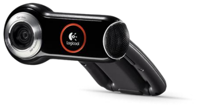
A Logitech QuickCam Pro 9000 camera was used when testing a camera via the USB interface.
Supported boards
The following boards support USB based cameras.
- iMX6 SoloX COM
- iMX6 Quad COM
- iMX6 DualLite COM
- iMX6 UltraLite COM
- iMX7 Dual COM
- iMX7 Dual uCOM
- iMX7ULP uCOM
- iMX8M Mini uCOM
- iMX8M Mini SOM
- iMX8M Nano uCOM
- iMX8M Quad COM
- iMX93 uCOM
Instructions
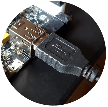
- Connect the camera to the USB host port on the carrier board as shown in the figure below
- The camera will be detected and you will see output in the console similar to below.
usb 1-1.1: USB disconnect, device number 3
usb 1-1.3: new high-speed USB device number 4 using ci_hdrc
uvcvideo: Found UVC 1.00 device <unnamed> (046d:0990)
input: UVC Camera (046d:0990) as /devices/soc0/soc/2100000.aipsbus/2184200.usb/ci_hdrc.1/usb1/1-1/1-1.3/1-1.3:1.0/input/input1
usbcore: registered new interface driver uvcvideo
USB Video Class driver (1.1.1)
usb 1-1.3: Warning! Unlikely big volume range (=3072), cval->res
is probably wrong.
usb 1-1.3: [5] FU [Mic Capture Volume] ch = 1, val = 4608/7680/1
usbcore: registered new interface driver snd-usb-audio
- Use
v4l2-ctlto find out on which video interface the camera is attached. In this example four interfaces are available and the USB camera (UVC Camera) is attached to/dev/video3.
v4l2-ctl --list-devices
i.MX6S_CSI (platform:2214000.csi):
       /dev/video1
i.MX6S_CSI (platform:221c000.csi):
       /dev/video2
pxp (pxp_v4l2_out):
       /dev/video0
UVC Camera (046d:0990) (usb-ci_hdrc.1-1.3):
       /dev/video3
- Use the command below to start capturing a video stream and show it on a display. If you don’t have a display, go to step 5 and take a snapshot instead.
For all iMX6 and iMX7 based boards
gst-launch-1.0 -v imxv4l2src device=/dev/video3 ! capsfilter caps="video/x-raw, width=640, height=480, framerate=30/1" ! queue ! imxv4l2sink
For iMX8M based boards
gst-launch-1.0 -v v4l2src device=/dev/video3 ! capsfilter caps="video/x-raw, width=640, height=480, framerate=30/1" ! queue ! autovideosink
- Use the command below to take a snapshot from the camera. The snapshot is stored as a jpeg file.
For all iMX6 and iMX7 based boards
gst-launch-1.0 imxv4l2src device="/dev/video3" num-buffers=1 ! capsfilter caps="video/x-raw, width=640, height=480, framerate=30/1" ! videoconvert ! jpegenc ! filesink location=snapshot.jpeg
For iMX8M based boards
gst-launch-1.0 v4l2src device="/dev/video3" num-buffers=1 ! capsfilter caps="video/x-raw, width=640, height=480, framerate=30/1" ! videoconvert ! jpegenc ! filesink location=snapshot.jpeg
- In the above examples a resolution of 640x480 and frame rate of 30 fps was used. You can query the camera to see which resolutions and frame rates it supports for different pixel formats. Only a portion of the output from the command is shown below.
v4l2-ctl --list-formats-ext -d /dev/video3
ioctl: VIDIOC_ENUM_FMT
        Index       : 0
        Type        : Video Capture
        Pixel Format: 'MJPG' (compressed)
        Name        : Motion-JPEG
                Size: Discrete 160x120
                       Interval: Discrete 0.033s (30.000 fps)
                       Interval: Discrete 0.040s (25.000 fps)
                       Interval: Discrete 0.050s (20.000 fps)
MIPI/CSI-2 interface
Camera
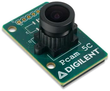
The Pcam 5C camera from Digilent was used when testing a camera with MIPI interface. This camera is using the Omnivision OV5640 image sensor. Two data lanes are connected. The camera comes with a (about) 200 mm long, 20-pos, 1 mm pitch flat cable.
Do not extend the cable length more than this. The total length of the MIPI/CSI-2 trace length should be kept less than 200 mm. This is due to the high frequency signals on the MIPI/CSI2 interface.
Supported boards
The following boards support MIPI/CSI-2 interface.
- iMX6 Quad COM
- iMX6 DualLite COM
- iMX7 Dual COM
- iMX7 Dual uCOM
- iMX8M Mini uCOM
- iMX8M Mini SOM
- iMX8M Nano uCOM
- iMX8M Quad COM
- iMX93 uCOM
Instructions
- Connect camera to the carrier board.
- COM Carrier Board V1/V2
- SOM Carrier Board
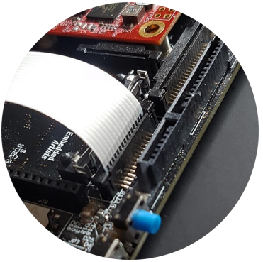
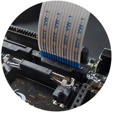
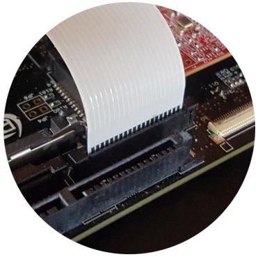
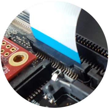
Connect the camera to the J20 connector if you are using COM Carrier Board V1 or to the J32 connector if you are using COM Carrier Board V2. Photos below are for COM Carrier Board V1, but it looks similar for COM Carrier Board V2. The exposed pads on the cable shall be mounted towards the nearby PCB edge. The first photo illustrates the exposed pads. The second photo illustrates the side of the cable without exposed pads.
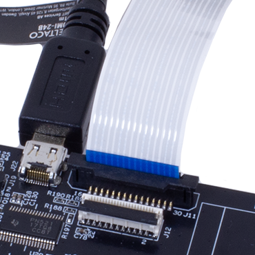
For the SOM Carrier Board, connect the camera to the J11 connector. This connector is located to the right of the micro-HDMI connector as shown in the photo below.
- Boot into the U-Boot. We need to change to a different dtb (device tree) file before booting into Linux. This new dtb file enables the MIPI/CSI-2 interface and adds the ov5640 camera to the I2C bus. In this example we are using an iMX6 Quad COM board. For other boards the name of the dtb file will be different. Change
imx6qea-com-kitto the name of the board you are using, for example,imx7dea-com-kitif you are using the iMX7 Dual COM board.
setenv fdt_file imx6qea-com-kit-ov5640.dtb
saveenv
If you want to see how the device file looks like you can find it on our GitHub repository.
- Reset the board and boot into Linux. When you have logged into Linux run the command below to see if the camera has been found. You should see the message
camera ov5640_mipi is found.
dmesg | grep ov5640
camera ov5640_mipi is found
- Use
v4l2-ctlto list available video interfaces. In this example three interfaces are listed, but no detailed information about each interface. The camera is in this case available on/dev/video0.
v4l2-ctl --list-devices
():
          /dev/video0
          /dev/video16
          /dev/video17
- Use the command below to start capturing a video stream and show it on a display. If you don't have a display, go to step 6 and take a snapshot instead.
For all iMX6 and iMX7 based boards
gst-launch-1.0 -v imxv4l2src device=/dev/video0 ! capsfilter caps="video/x-raw, width=640, height=480, framerate=30/1" ! queue ! imxv4l2sink
iMX8M Mini based boards
- Pre 6.12.3
- 6.12.3 and newer
gst-launch-1.0 -v v4l2src device=/dev/video0 ! capsfilter caps="video/x-raw, width=640, height=480, framerate=30/1" ! queue ! autovideosink
media-ctl -l "'ov5640 0-003c':0 -> 'csis-32e30000.mipi-csi':0 [1]"
media-ctl -V "'ov5640 0-003c':0 [fmt:YUYV8_1X16/640x480 field:none]"
media-ctl -V "'csis-32e30000.mipi-csi':0 [fmt:YUYV8_1X16/640x480 field:none]"
media-ctl -V "'csi':0 [fmt:YUYV8_1X16/640x480 field:none]"

gst-launch-1.0 v4l2src device=/dev/video0 ! video/x-raw,width=640,height=480,format=YUY2 ! waylandsink
iMX8M Nano based boards
- Pre 6.12.3
- 6.12.3 and newer
gst-launch-1.0 -v v4l2src device=/dev/video0 ! capsfilter caps="video/x-raw, width=640, height=480, framerate=30/1" ! queue ! autovideosink
media-ctl -l "'ov5640 0-003c':0 -> 'csis-32e30000.mipi-csi':0 [1]"
media-ctl -V "'ov5640 0-003c':0 [fmt: UYVY8_1X16/640x480 field:none]"
media-ctl -V "'csis-32e30000.mipi-csi':0 [fmt: UYVY8_1X16/640x480 field:none]"
media-ctl -V "'crossbar':0 [fmt: UYVY8_1X16/640x480 field:none]"
media-ctl -V "'mxc_isi.0':0 [fmt: UYVY8_1X16/640x480 field:none]"

gst-launch-1.0 v4l2src device=/dev/video0 ! video/x-raw,width=640,height=480,format=YUY2 ! waylandsink
iMX93 based boards
- Pre 6.12.3
- 6.12.3 and newer
gst-launch-1.0 -v v4l2src device=/dev/video0 ! capsfilter caps="video/x-raw, width=640, height=480, framerate=30/1" ! queue ! autovideosink
media-ctl -l "'ov5640 0-003c':0->'csidev-4ae00000.csi':0 [1]"
media-ctl -V "'ov5640 0-003c':0 [fmt: UYVY8_1X16/720x480 field:none]"
media-ctl -V "'csidev-4ae00000.csi':0 [fmt: UYVY8_1X16/720x480 field:none]"
media-ctl -V "'crossbar':0 [fmt: UYVY8_1X16/720x480 field:none]"
media-ctl -V "'mxc_isi.0':0 [fmt: UYVY8_1X16/720x480 field:none]"

gst-launch-1.0 v4l2src device=/dev/video0 ! video/x-raw,width=720,height=480,format=YUY2 ! waylandsink
- Use the command below to take a snapshot from the camera. The snapshot is stored as a jpeg file.
For all iMX6 and iMX7 based boards
gst-launch-1.0 imxv4l2src device="/dev/video0" num-buffers=1 ! capsfilter caps="video/x-raw, width=640, height=480, framerate=30/1" ! videoconvert ! jpegenc ! filesink location=snapshot.jpeg
For iMX8M based boards
gst-launch-1.0 v4l2src device="/dev/video0" num-buffers=1 ! capsfilter caps="video/x-raw, width=640, height=480, framerate=30/1" ! videoconvert ! jpegenc ! filesink location=snapshot.jpeg
Parallel interface
Camera
The Waveshare OV5640 Camera Board was used when testing a camera with parallel interface. This camera is using the Omnivision OV5640 image sensor. This sensor supports both the MIPI/CSI-2 and parallel camera interface. On the Waveshare board, the parallel interface is connected.
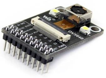
Please note that this board cannot be connected directly to the connector on Embedded Artists COM Carrier board. You need to make an adapter between the camera board and the COM Carrier board.
Also note that the camera must be supplied with a 24 MHz clock with 2.8V voltage level. A 3.3V logic level clock will create disturbances in the camera. A local 24 MHz oscillator, powered by 2.8V, can be placed on the adapter between the Waveshare module and COM Carrier board.
Note that the parallel camera interface cannot be extended more than 100 mm from the MXM3 connector. Depending on pixel clock frequency, it can even be shorter than this. In general, Embedded Artists recommend using the MIPI/CSI-2 interface when connecting a camera.
Supported boards
The following boards support cameras with parallel interface.
iMX7 Dual COM and iMX7 Dual uCOM boards also support parallel interface, but not in combination with the Embedded Artists' COM Carrier Board.
Instructions
If you are using iMX6 Quad COM or iMX6 DualLite COM you cannot have the camera inserted into the J21/J34 during a reset / power-cycle. The board will enter USB boot mode and not boot from eMMC. You can boot into U-Boot, insert the camera and then continue and boot into Linux.
Contact Embedded Artists for more details.
- Connect the camera to the J21 connector if you are using COM Carrier Board V1 or to the J34 connector if you are using COM Carrier Board V2. The two photors below are for COM Carrier Board V1, but it looks similar for COM Carrier Board V2.
- Boot into the U-Boot. We need to change to a different dtb (device tree) file before booting into Linux. This new dtb file enables the parallel interface and adds the ov5640 camera to the I2C bus. In this example we are using an iMX6 SoloX COM board. For other boards the name of the dtb file will be different. Change
imx6sxea-com-kitto the name of the board you are using, for example,imx6qea-com-kitif you are using the iMX6 Quad COM board.
setenv fdt_file imx6sxea-com-kit-ov5640-pl.dtb
saveenv
If you want to see how the device file looks like you can find it on our GitHub repository.
- Reset the board and boot into Linux. When you have logged into Linux run the command below to see if the camera has been found. You should see the message
camera ov5640, is found.
dmesg | grep ov5640
camera ov5640, is found
- Use
v4l2-ctlto list available video interfaces. In this example three interfaces are listed, but no detailed information about each interface. The camera is in this case available on/dev/video1.
v4l2-ctl --list-devices
i.MX6S_CSI (platform:2214000.csi):
         /dev/video1
i.MX6S_CSI (platform:221c000.csi):
         /dev/video2
pxp (pxp_v4l2_out):
         /dev/video0
- Use the command below to start capturing a video stream and show it on a display. If you don't have a display, go to step 6 and take a snapshot instead.
gst-launch-1.0 -v imxv4l2src device=/dev/video1 ! capsfilter caps="video/x-raw, width=640, height=480, framerate=30/1" ! queue ! imxv4l2sink
- Use the command below to take a snapshot from the camera. The snapshot is stored as a jpeg file.
gst-launch-1.0 imxv4l2src device="/dev/video1" num-buffers=1 ! capsfilter caps="video/x-raw, width=640, height=480, framerate=30/1" ! videoconvert ! jpegenc ! filesink location=snapshot.jpeg