eMMC flash
Introduction
Most embedded devices need some kind of storage area for firmware and data files. Many different solutions exist, but this guide will focus on embedded MultiMediaCard normally referred to as eMMC.
An eMMC consists of two parts; the flash memory (of type NAND) and the memory controller. Having the memory controller integrated simplifies the usage of the storage device. Without this controller the software driver on the host would have to handle the low-level flash memory management, such as wear levelling and error correction.
Additional information
Additional documentation you might need is.
- "TN-52-07: e.MMC Partitioning", from Micron
- "TN-FC-40: Configuring the Embedded e.MMC Device", from Micron
- "TN-FC-06: Booting from Embedded MMC", from Micron
- Introduction of eMMC by Yejin Moon at Samsung Electronics
Default configuration
Memory areas
When the eMMC component is delivered from the manufacturer it is normally divided into four areas as shown in the figure below.
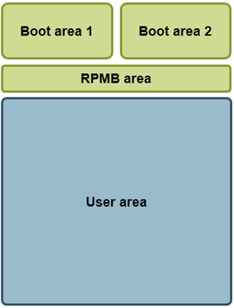
| Area | Description |
|---|---|
| Boot | Typically used to store firmware and data needed during booting of the device. Two boot areas are normally available, and these are of type SLC NAND (enhanced mode) |
| RPMB | Replay-protected memory-block area. This area is typically used to store secure data such as encryption keys. This area is of type SLC NAND (enhanced mode). |
| User | This area is used to store user data such as a file system. This is the area that is normally divided into several partitions. By default, it is of type MLC NAND, but can be changed to SLC NAND (enhanced mode), see Create enhanced mode (SLC). |
Usage of the areas
The figure below show the default usage of the eMMC areas on Embedded Artists COM boards.
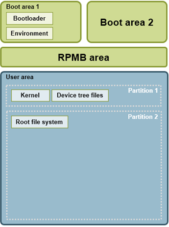
| Area | Description |
|---|---|
| Boot area 1 | The bootloader images (such as SPL and U-Boot) are stored in this area. The boot area is not formatted and contains no file system. The images are instead stored at fixed offsets. When SPL and U-Boot are used SPL will be stored at an offset of 1024 bytes (1 Kbyte) and U-Boot will be stored at an offset of 69 Kbytes. The area also contains the U-Boot environment which is stored at an offset of 2 Mbytes minus 8 Kbytes (2MB – 8KB). |
| User area Partition 1 | The user area is divided into two partitions. The first partition will be FAT32 formatted and contain the Linux kernel and device tree files. |
| User area Partition 2 | The second partition contains the root file system and is by default ext3 formatted. |
Get information
List MMC devices
In Linux you can list available MMC devices (and partitions) by checking the /dev/ directory.
ls -la /dev/mmcblk*
brw-rw----    1 root     disk      179,   0 Dec 23 11:57 /dev/mmcblk2
brw-rw----    1 root     disk      179,  32 Dec 23 11:57 /dev/mmcblk2boot0
brw-rw----    1 root     disk      179,  64 Dec 23 11:57 /dev/mmcblk2boot1
brw-rw----    1 root     disk      179,   1 Dec 23 11:57 /dev/mmcblk2p1
brw-rw----    1 root     disk      179,   2 Dec 23 11:57 /dev/mmcblk2p2
brw-rw----    1 root     disk      179,  96 Dec 23 11:57 /dev/mmcblk2rpmb
In the above example there is one MMC device (mmcblk2) which has 5 partitions.
mmc-utils
The tool mmc-utils is by default installed in the root file system when using Embedded Artists Yocto image. This tool can be used not only to retrieve information about the eMMC device, but also change its configuration.
Check eMMC version
In the example below we can see that the eMMC version is 5.1.
mmc extcsd read /dev/mmcblk2 | head 2
=============================================
  Extended CSD rev 1.8 (MMC 5.1)
Max Enhanced Area Size
You can check the maximum enhanced area size that can be used (see Create enhanced mode (SLC) for more information about enhanced area).
mmc extcsd read /dev/mmcblk2 | grep -A2 MAX_ENH_SIZE_MULT
Max Enhanced Area Size [MAX_ENH_SIZE_MULT]: 0x0001d2
 i.e. 3817472 KiB
Boot partition size
Check the boot partition size by running the command below. You can then calculate the actual size by 128 KB x BOOT_SIZE_MULTI. In the example below the size is 128 KB x 64 = 8192 KB = 8 MB.
mmc extcsd read /dev/mmcblk2 | grep BOOT_SIZE_MULTI
Boot partition size [BOOT_SIZE_MULTI: 0x40]
Boot configuration
Check the current boot configuration by running the command below. In this example BOOT_ACK (bit 6) is set and boot partition 1 is enabled (bit 3). See the table below for the field / bit descriptions.
mmc extcsd read /dev/mmcblk2 | grep PARTITION_CONFIG
Boot configuration bytes [PARTITION_CONFIG: 0x48]
| Bit | Field | Description |
|---|---|---|
| 6 | BOOT_ACK |
|
| [5:3] | BOOT_PARTITION_ENABLE |
|
| [2:0] | BOOT_PARTITION_ACCESS |
|
Life time estimation
It is possible to get an estimation on the health status of the device by checking the parameters EXT_CSD_DEVICE_LIFE_TIME_EST_TYP_A and EXT_CSD_DEVICE_LIFE_TIME_EST_TYP_B. The estimation is given in steps of 10% so a value of 0x01 means that 0% to 10% life time used. This functionality was introduced in eMMC 5.0.
mmc extcsd read /dev/mmcblk2 | grep EXT_CSD_DEVICE_LIFE_TIME_EST
eMMC Life Time Estimation A [EXT_CSD_DEVICE_LIFE_TIME_EST_TYP_A]: 0x01
eMMC Life Time Estimation B [EXT_CSD_DEVICE_LIFE_TIME_EST_TYP_B]: 0x01
fdisk
The tool fdisk can be used to manage partitions in Linux. In the example below the available partition are listed. In the example you can see that one disk (device) is available (mmcblk2) and a total of 5 partitions (same as was listed in the List MMC devices section above). You can also see the file system type being used (mmcblk2p1 is for example FAT32 formatted) and the size of the partition.
fdisk -l
Disk /dev/mmcblk2: 7456 MB, 7818182656 bytes, 15269888 sectors
238592 cylinders, 4 heads, 16 sectors/track
Units: cylinders of 64 * 512 = 32768 bytes

Device       Boot StartCHS    EndCHS        StartLBA     EndLBA    Sectors  Size Id Type
/dev/mmcblk2p1    320,0,1     959,3,16         20480    1044479    1024000  500M  c Win95 FAT32 (LBA)
/dev/mmcblk2p2    768,0,1     1023,3,16      1228800   15269887   14041088 6856M 83 Linux
Disk /dev/mmcblk2rpmb: 4 MB, 4194304 bytes, 8192 sectors
128 cylinders, 4 heads, 16 sectors/track
Units: cylinders of 64 * 512 = 32768 bytes

Disk /dev/mmcblk2rpmb doesn't contain a valid partition table
Disk /dev/mmcblk2boot1: 8 MB, 8388608 bytes, 16384 sectors
256 cylinders, 4 heads, 16 sectors/track
Units: cylinders of 64 * 512 = 32768 bytes

Disk /dev/mmcblk2boot1 doesn't contain a valid partition table
Disk /dev/mmcblk2boot0: 8 MB, 8388608 bytes, 16384 sectors
256 cylinders, 4 heads, 16 sectors/track
Units: cylinders of 64 * 512 = 32768 bytes

Disk /dev/mmcblk2boot0 doesn't contain a valid partition table
df
The tool df (disk free) can be used to see available storage space. In this example the root file system has 5.8 GByte available.
df -h
Filesystem                Size      Used Available Use% Mounted on
/dev/root                 6.5G    416.3M      5.8G   7% /
devtmpfs                173.9M         0    173.9M   0% /dev
tmpfs                   494.2M         0    494.2M   0% /dev/shm
tmpfs                   494.2M     16.4M    477.9M   3% /run
tmpfs                   494.2M         0    494.2M   0% /sys/fs/cgroup
tmpfs                   494.2M    756.0K    493.5M   0% /tmp
tmpfs                   494.2M     24.0K    494.2M   0% /var/volatile
tmpfs                    98.8M     88.0K     98.8M   0% /run/user/0
mount
With the tool mount you can see which partitions that have been mounted in the file system. In the example below we see that partition 2 of the mmcblk2 device (eMMC) is mounted and has an ext3 filesystem.
mount | grep mmc
/dev/mmcblk2p2 on / type ext3 (rw,relatime,data=ordered)
Create and modify partitions
Partition user area
By default, the user area will be split into two partitions. This is done in the UUU scripts provided by Embedded Artists.
The example below is from full_tar.uuu for the iMX8M Mini uCOM board.
FBK: ucmd mmc=`cat /tmp/mmcdev`; PARTSTR=$'10M,500M,0c\n600M,,83\n'; echo "$PARTSTR" | sfdisk --force /dev/mmcblk${mmc}
The tool sfdisk is used to do the partitioning and it is given a string with two lines. Each line will create a partition. In this example each line contains three arguments: <start>, <size>, and <id>.
10M,500M,0c means start at offset 10 MB with a size of 500 MB. The id is 0x0c which means FAT32. This first partition will in the default setup contain Kernel and device tree files.
600M,..,83 means start at offset 600 MB and the size will be the remaining size of the user area. The id is 0x83 which means Linux native partition. This second partition will in the default setup contain the root file system.
Partition type IDs: https://en.wikipedia.org/wiki/Partition_type
Switch boot partition
The default setup from Embedded Artists is to have boot partition 1 enabled for boot. See the Boot configuration section for how to get information about current boot configuration.
Changing boot configuration can be done from Linux by using mmc-utils and more specifically mmc bootpart enable <boot_partition> <send_ack> <device>. In the example below boot partition 1 is enabled with boot acknowledgement for device /dev/mmcblk2.
mmc bootpart 1 1 /dev/mmcblk2
Please note that you must also make sure to program the boot partition with bootable image(s). There are different ways to do this, but you could for example use the UUU scripts provided by Embedded Artists for the board you are using.
The excerpt below is from the bootloader.uuu script for the iMX7 Dual uCOM board. You can in this example see that boot partition 1 is used (the device name ends with boot0). You can also see that mmc utils is used to enable boot partition 1 for boot.
If you instead want to use boot partition 2 you can replace boot0 with boot1 and make sure mmc-utils enable partition 2 (mmc bootpart enable 2 1 /dev/mmcblk${mmc}).
All boot0 must be changed to boot1 and not just the highlighted parts.
# erase u-boot environment (8Kb located at offset (2Mb-8Kb) on /dev/mmcblk*boot0)
FBK: ucmd mmc=`cat /tmp/mmcdev`; echo 0 > /sys/block/mmcblk${mmc}boot0/force_ro
FBK: ucmd mmc=`cat /tmp/mmcdev`; dd if=/dev/zero of=/dev/mmcblk${mmc}boot0 bs=1k seek=2040 count=8
# bootloaders (SPL + u-boot)
FBK: ucp files/SPL-imx7dea-ucom t:/tmp
FBK: ucmd mmc=`cat /tmp/mmcdev`; dd if=/tmp/SPL-imx7dea-ucom of=/dev/mmcblk${mmc}boot0 bs=512 seek=2
FBK: ucp files/u-boot-imx7dea-ucom.img t:/tmp
FBK: ucmd mmc=`cat /tmp/mmcdev`; dd if=/tmp/u-boot-imx7dea-ucom.img of=/dev/mmcblk${mmc}boot0 bs=512 seek=138
FBK: ucmd mmc=`cat /tmp/mmcdev`; echo 1 > /sys/block/mmcblk${mmc}boot0/force_ro
FBK: ucmd mmc=`cat /tmp/mmcdev`; mmc bootpart enable 1 1 /dev/mmcblk${mmc}
Create enhanced mode (SLC)
Why enhanced mode?
The eMMC is built using NAND flash technology which exists in two different types; Single-Level Cell (SLC) or Multi-Level Cell (MLC). MLC flash was developed to offer higher capacity (larger flash size) for a given die size which basically means lower cost. SLC on the other hand provides better reliability and performance making it in general more suitable for embedded and industrial products.
The disadvantage of configuring the user data area to enhanced mode is that you lose half of the storage size.
Create partition from Linux
The instructions in this document have been tested on Embedded Artists 4.14.98 distribution.
The mmc-utils tool will be used to create an enhanced mode partition on the eMMC. These tools are already added to Embedded Artists Yocto image (ea-image-base). If you want to add it to your own custom build include the package below to your conf/local.conf file.
IMAGE_INSTALL_append = " \
    mmc-utils \
"
The instructions below are irreversible. Once you have converted a partition to enhanced mode you can never undo this operation. Double check your parameters before executing a command!
-
Find the eMMC device.
By default, the eMMC device is mounted as root device. If you run the
mountcommand you can in this example see that MMC block device 2 (mmcblk2p2) and more specifically partition 2 (mmcblk2p2) is mounted as root device.mount | grep mmc/dev/mmcblk2p2 on / type ext3 (rw,relatime,data=ordered) -
Finding the maximum size of the enhanced area.
Only a portion of the output from the mmc extcsd command is shown below. The important value is the
Max Enhanced Area Sizevalue which in this example is 1908736 KiB (the total size of the eMMC is in this example 4 GB).noteWhen converting the user area to enhanced mode you will only get half the size of the original area.
mmc extcsd read /dev/mmcblk2=============================================
Extended CSD rev 1.7 (MMC 5.0)
=============================================
Card Supported Command sets [S_CMD_SET: 0x01]
...
Max Enhanced Area Size [MAX_ENH_SIZE_MULT]: 0x0000e9
i.e. 1908736 KiB
Partitions attribute [PARTITIONS_ATTRIBUTE]: 0x00
Partitioning Setting [PARTITION_SETTING_COMPLETED]: 0x00
Device partition setting NOT complete -
Convert to enhanced mode.
mmc enh_area set -y 0 1908736 /dev/mmcblk2 -
Power-cycle and re-program.
You need to power-cycle the board for the operation to take effect. Please note that you will also have to re-program the board (partition, format, and program kernel and file system) using for example manufacturing tool (UUU).
Create partition from U-Boot
The instructions in this document have been tested using U-Boot 2018.03.
The instructions below are irreversible. Once you have converted a partition to enhanced mode you can never undo this operation. Double check your parameters before executing a command!
These instructions will convert the entire user area to enhanced mode. If you want to convert only a portion of the area you need to modify the start and the cnt arguments.
-
Find the eMMC device.
In this example you can see that eMMC is available on mmc device 1.
mmc listFSL_SDHC: 0
FSL_SDHC: 1 (eMMC)mmc dev 1switch to partitions #0, OK
mmc1(part 0) is current device -
Finding the maximum size of the enhanced area.
noteWhen converting the user area to enhanced mode you will only get half the size of the original area.
The best way to find this value is from within Linux as described in the Create partition from Linux section above.
Using
mmc infodoesn't give an accurate value. As seen below the value forUser Capacityis rounded to one decimal (3.6GiB). An accurate value would have been 3.640625 GiB (3728 MiB or 3817472 KiB) which could then be use to get the maximum value of the enhanced area, that is, half the value of the original area. Note that when using themmc hwpartitioncommand you need to give all values in 512-byte blocks.mmc infoDevice: FSL_SDHC
Manufacturer ID: 13
OEM: 14e
Name: Q1J54
Tran Speed: 52000000
Rd Block Len: 512
MMC version 5.0
High Capacity: Yes
Capacity: 3.6 GiB
Bus Width: 8-bit
Erase Group Size: 512 KiB
HC WP Group Size: 8 MiB
User Capacity: 3.6 GiB WRREL
Boot Capacity: 2 MiB ENH
RPMB Capacity: 512 KiB ENH -
Convert to enhanced mode.
mmc hwpartition user enh 0 3817472 completePartition configuration:
User Enhanced Start: 0 Bytes
User Enhanced Size: 1.8 GiB
No GP1 partition
No GP2 partition
No GP3 partition
No GP4 partition -
Power-cycle and re-program.
You need to power-cycle the board for the operation to take effect. Please note that you will also have to re-program the board (partition, format, and program kernel and file system) using for example manufacturing tool (UUU).