Mount and unmount a uCOM board
This guide describes how you can safely mount and unmount a uCOM board from a carrier board.
Unmount
Preparations
First make sure you work in an ESD safe environment placing the uCOM board on an anti-static mat. You should also have a wrist strap attached to your wrist and the anti-static mat.
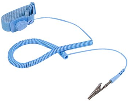
To disconnect the board, you can use for example a screwdriver with a flat head. Make sure the flat head is at least 3 mm wide and that the screwdriver doesn't have any sharp corners that can damage the PCB.
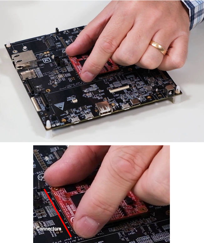
Place fingers over connectors
Begin by placing your fingers over the connectors to counteract big movements. In the figure below you can see where the connectors are located and how to place your fingers.
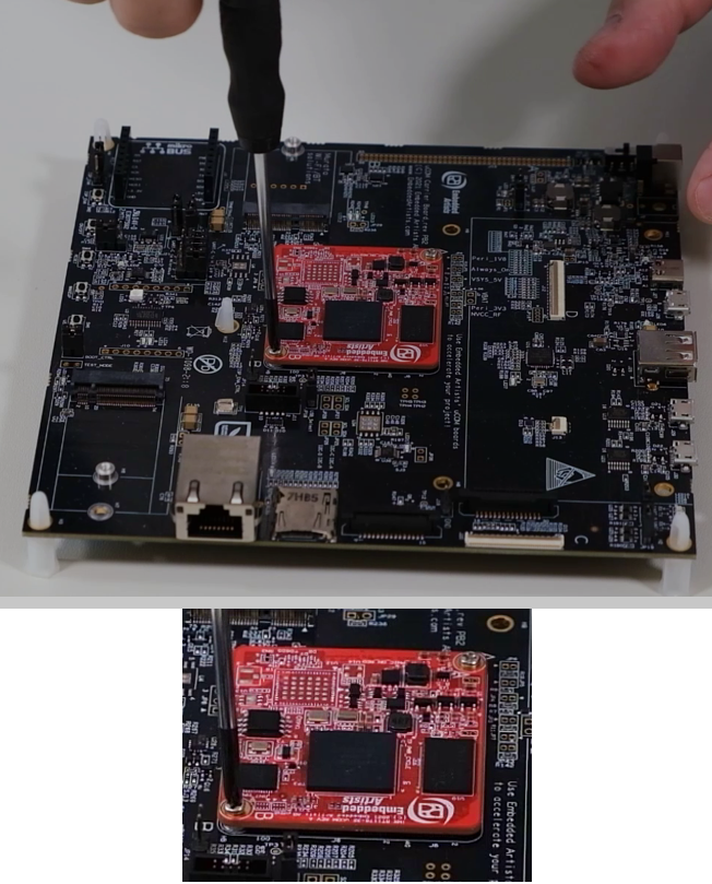
Place tool in middle of PCB
Place the screwdriver in the middle of the uCOM board as shown in the figure below. Gently turn the screwdriver until the connectors disconnects. You may hear a click sound when it disconnects.
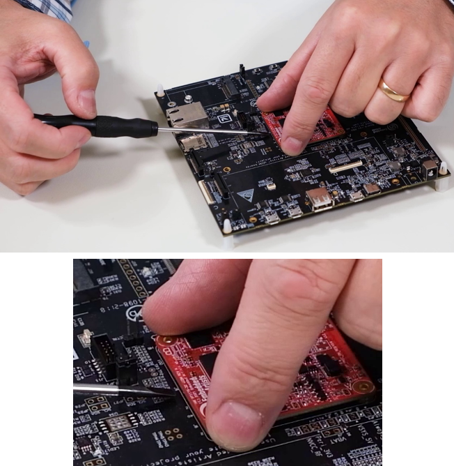
Do not turn the screwdriver more than the first click sound (then the connectors disconnect). Keep the uCOM boards as close as possible to the connector on the carrier board. Do not do any big movements.
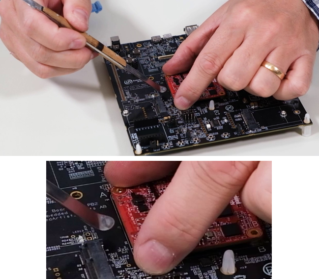
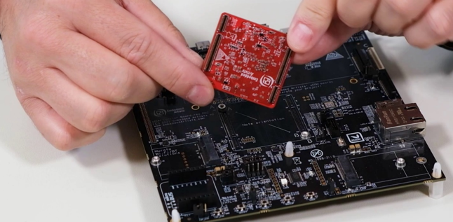
Turn the board around to disconnect the other side. In the figure below there is an example of another tool. Do the same, that is, place the tool in the middle of the PCB and use small movements to disconnect the connectors.
The board is now fully unmounted and can easily be removed. You should put it in an ESD bag or ESD safe environment immediately.
Mount
Orientation of board
There are stringent requirements on how relative to each other the connectors are mounted on the uCOM board and carrier board. See the datasheet for details before designing your carrier board.
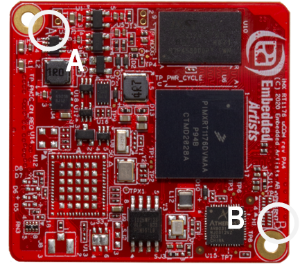
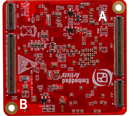
Before mounting the board, you must identify the A- and the B-corner on the uCOM board. There is an A and B on the PCB as you can see in the circles in the figure below.
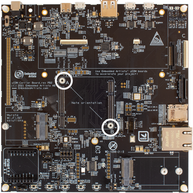
There is also an A- and a B-marking on the uCOM carrier board as shown in the figure below. It is recommended that you put an A- and B-marking in the silk screen on your carrier board to avoid mounting the uCOM board incorrectly.
It is possible to mount the board incorrectly. It will look almost perfectly, but the corner holes will be a bit misaligned. If the uCOM board is mounted incorrectly and powered the board will be irreparable.
Find connectors
With the correct orientation place the uCOM board above the connectors and then with all four fingers feel where the connectors meet. You will find a position when there the uCOM board will rest in the connector positions on the carrier board. You can then also see that the corners are aligned with the holes.
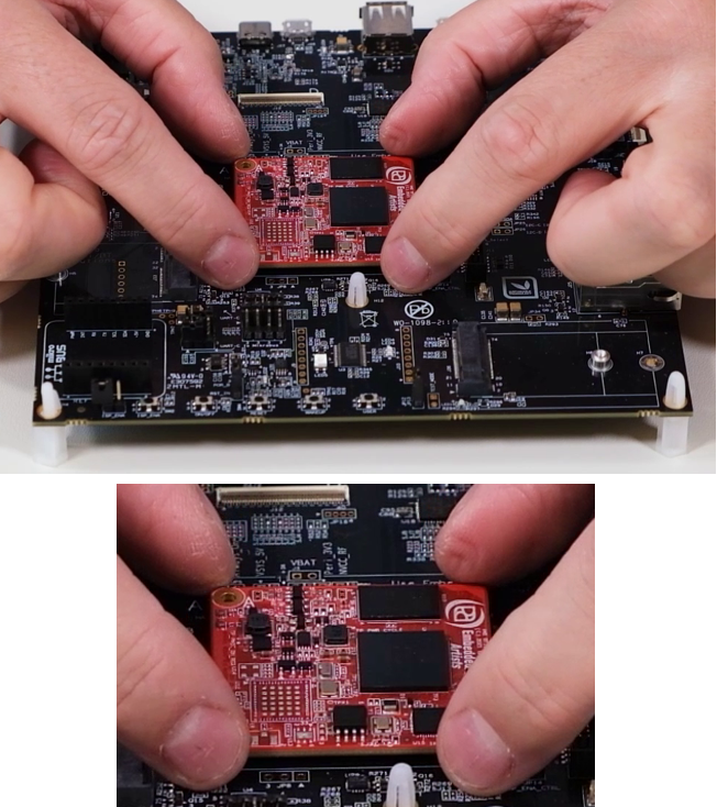
Connect the board
Start with one of the edges and put your fingers above the connectors about 10 mm in from the corners. Gently press until the connectors are connected. You may hear a click sound. Repeat and do the same thing on the other edge.
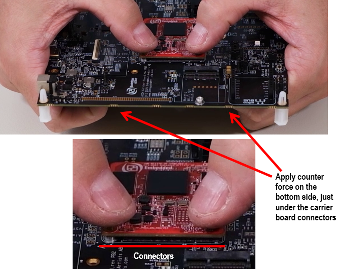
It is very important to apply a counter force on the bottom side, under the carrier board connectors. If not, the risk is high that the carrier board is bent when pressing the uCOM board into the connectors. Bending on the carrier board can easily damage the connectors and the copper tracks on the carrier board.
The counter force does not need to come from hands. It can come from stand-offs close to the carrier board connectors or from a fixture used during uCOM board mounting.
Mount screws in corner holes
As a final step you can mount screws in the corner holes. Tighten the screws, but don't use too much force because then you can damage the PCB.
Be careful with the screwdriver. If it lose the grip on the screw it can easily damage components on the uCOM board.
Use a heat sink
If you would like to mount a heat sink on the processor, design the heat transfer management system so that the heat sink doesn’t push down on the processor and bend the uCOM PCB when the heat increases (and materials expand).
Use spring loaded screws, push pins or captive screws when mounting the heat sink in order to get a precise and constant pressure on the processor even if some of the material expand when temperature increase.
Alternatively use a thermal interface material (TIM) that is thicker and designed to absorb material expansion