Sleep mode to running
Besides the boot time it is also of interest to know the time it takes to wake up from a sleep mode (power-saving mode). This is for example useful if you don’t want to power down the system completely, but instead set the system into a sleep mode in order to save power.
More information about sleep modes:
https://www.kernel.org/doc/html/v5.4/admin-guide/pm/sleep-states.html
Summary
The table below lists the time it takes to wake up from a certain sleep mode for a standard, unmodified ea-image-base build. The value is number of milliseconds since a trigger point (key pressed on keyboard) until an application toggling a GPIO starts toggling the GPIO again.
Build details
- Date: 2020-09-17
- Linux: 5.4.24
- U-Boot: 2020.04
- meta-ea commit: d5dcc59ee673ad99e99da892f79ce0966f1c3b61
| Sleep mode | iMX8M Mini | iMX8M Nano | iMX8M | iMX6 Quad | iMX6 DualLite | iMX6 SoloX | iMX6 UltraLite | iMX7 Dual COM | iMX7 Dual uCOM | iMX7ULP |
|---|---|---|---|---|---|---|---|---|---|---|
| Standby | - | - | - | 88 | 87 | 95 | 89 | 98 | 94 | - |
| Suspend-to-Idle | 82 | 15 | 1254 | 78 | 82 | 90 | 94 | 83 | 81 | 88 |
| Suspend-to-RAM | 96 | 29 | 1274 | 94 | 94 | 99 | 89 | 97 | 97 | 283 |
In the table below the USB interface connected to the USB hub on the carrier board has been disabled (in the device tree file). As you can see the wakeup time is much lower so the USB hub is causing delays.
| Sleep mode | iMX8M Mini | iMX8M Nano | iMX8M | iMX6 Quad | iMX6 DualLite | iMX6 SoloX | iMX6 UltraLite | iMX7 Dual COM | iMX7 Dual uCOM | iMX7ULP |
|---|---|---|---|---|---|---|---|---|---|---|
| Standby | - | - | - | 24 | 24 | 26 | 35 | 21 | 25 | - |
| Suspend-to-Idle | 17 | - | 11 | 12 | 17 | 18 | 17 | 9 | 14 | - |
| Suspend-to-RAM | 31 | - | 21 | 27 | 30 | 30 | 28 | 26 | 28 | - |
How was it measured
A shell script was created that toggles a GPIO. The board was then configured to wake up via the TTY (UART) used by the console and then put to sleep with one of the commands described in section 5.2.3 below. When sending a character (by pressing a key on the keyboard) the board was brought up from sleep and the shell script started running again.
A logic analyzer was used and setup to trigger on a character being sent on the TTY. The time from this trigger point until the GPIO started to toggle was measured. See section 5.2.5 for information about where the UART signal can be measured on the expansion connector.
Shell script toggling GPIO
A simple shell script was created that toggles a GPIO as fast as possible. The example below is for the iMX8M Mini uCOM board and the script begins by setting up the GPIO to use. Table 6 below lists GPIO'’'s and TTY’s for all the boards.
#!/bin/bash

echo "Starting"

# GPIO 2.10 -> (2-1)*32+10=42
echo 42 > /sys/class/gpio/export
echo high > /sys/class/gpio/gpio42/direction

while :
do
        echo 0 > /sys/class/gpio/gpio42/value
        echo 1 > /sys/class/gpio/gpio42/value
done
The application was started by.
chmod a+x myapp.sh
./myapp.sh &
GPIO's and TTY
The same GPIO has been used when measuring wakeup time as was used when measuring boot time as described in section 3.3 and Table 2.
| Processor pin | Linux pin | TTY | |
|---|---|---|---|
| iMX8M Mini uCOM | GPIO 2.10 | 42 | ttymxc1 |
| iMX8M Nano uCOM | GPIO 2.10 | 42 | ttymxc1 |
| iMX8M Quad COM | GPIO 3.15 | 79 | ttymxc0 |
| iMX6 Quad COM | GPIO 4.08 | 104 | ttymxc3 |
| iMX6 DualLite COM | GPIO 4.08 | 104 | ttymxc3 |
| iMX6 SoloX COM | GPIO 4.27 | 123 | ttymxc0 |
| iMX6 UltraLite COM | GPIO 4.11 | 107 | ttymxc0 |
| iMX7 Dual COM | GPIO 2.18 | 50 | ttymxc0 |
| iMX7 Dual uCOM | GPIO 2.18 | 50 | ttymxc0 |
Commands
The commands below were run in Linux during measurement.
Activate wakeup from TTY. Change the TTY to the one valid for the board being tested. Below is valid for the iMX8M Mini uCOM board.
echo enabled > /sys/class/tty/ttymxc1/power/wakeup
Suspend to Standby
echo standby > /sys/power/state
Suspend to Idle
echo freeze > /sys/power/state
Suspend to RAM
echo mem > /sys/power/state
iMX7ULP uCOM
The iMX7ULP processor is different since the Cortex-M4 is the main core while for the other processors it is the Cortex-A core. Because of this the process of measuring the wakeup time is a bit different.
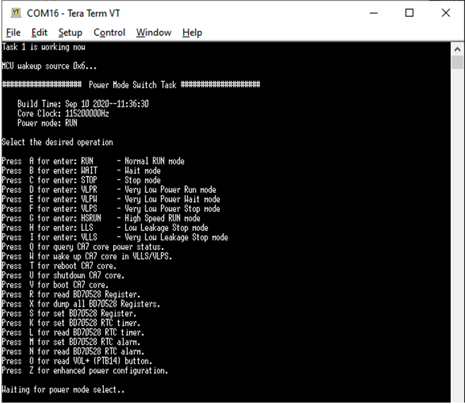
The application, that by default, is running on the Cortex-M4 can wake up the Cortex-A7 core. We will use this feature instead of using wakeup from TTY. See Figure 4 for the menu being presented by the application running on the Cortex-M4 core. Pressing W will wake up the Cortex-A7 core.
The wakeup time is measured as the time between pressing W (console connected to Cortex-M4) and the time when the first character is outputted from the Cortex-A7 core. See section 5.2.5 for information about where a UART signal can be measured on the expansion connector.
UART /TTY pins on expansion connector
The table below lists the UART pins that was used during measurements of wakeup times. The last column specifies where the signal can be found on the expansion board connected to the COM carrier board V2.
| Description | Expansion board | |
|---|---|---|
UART-A_RXD | Data sent from console application to Linux (Cortex-A core). Used to detect when a user presses a key on keyboard to wake up Linux from sleep mode. | J48-49 |
UART-A_TXD | Data sent from Linux to console application. For iMX7ULP this pin is used to detect when the Cortex-A core wakes up. | J48-74 |
UART-C_RXD | UART connected to the Cortex-M4 core on iMX7ULP. Used to detect when pressing ‘W’ on keyboard to inform the Cortex-M4 application to wake up the Cortex-A core. | J48-72 |