Analog Output - PWM
- COM Carrier Board V1
- COM Carrier Board V2
- uCOM Carrier Board V3
- SOM Carrier Board
| Board | Channels | Example PWM | pwmchipX |
|---|---|---|---|
| iMX6 SoloX COM | 8 | pwm1 | pwmchip0 |
| iMX6 Quad COM | 4 | pwm1 | pwmchip0 |
| iMX6 DualLite COM | 4 | pwm1 | pwmchip0 |
| iMX6 UltraLite COM | 8 | pwm1 | pwmchip0 |
| iMX7 Dual (u)COM | 4 | pwm3 | pwmchip1 |
| iMX7ULP uCOM | N/A | N/A | N/A |
| iMX8M Quad COM | 4 | pwm1 | pwmchip0 |
| iMX8M Mini uCOM | 4 | pwm1 | pwmchip0 |
| iMX8M Nano uCOM | 4 | pwm1 | pwmchip0 |
To use the PWM channels they must first be configured and enabled in the device tree. The scope of how to do that is beyond this document.
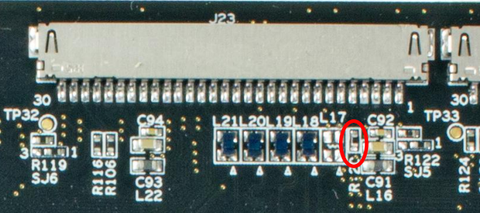
The table above list one example PWM that is enabled on all boards (backlight for LVDS). All COM boards have this on pin P138/284 of the MXM3 connector and the signal can be observed on resistor R120.
| Board | Channels | Example PWM | pwmchipX |
|---|---|---|---|
| iMX6 SoloX COM | 8 | pwm1 | pwmchip0 |
| iMX6 Quad COM | 4 | pwm1 | pwmchip0 |
| iMX6 DualLite COM | 4 | pwm1 | pwmchip0 |
| iMX6 UltraLite COM | 8 | pwm1 | pwmchip0 |
| iMX7 Dual (u)COM | 4 | pwm3 | pwmchip1 |
| iMX7ULP uCOM | N/A | N/A | N/A |
| iMX8M Quad COM | 4 | pwm1 | pwmchip0 |
| iMX8M Mini uCOM | 4 | pwm1 | pwmchip0 |
| iMX8M Nano uCOM | 4 | pwm1 | pwmchip0 |
To use the PWM channels they must first be configured and enabled in the device tree. The scope of how to do that is beyond this document.
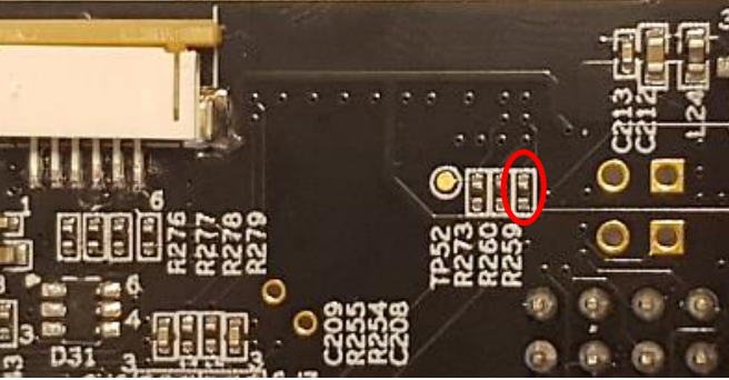
The table above list one example PWM that is enabled on all boards (backlight for LVDS). All COM boards have this on pin P138/284 of the MXM3 connector and the signal can be observed on resistor R259 which can be found on the back side.
| Board | Channels | Example PWM |
|---|---|---|
| iMX8M Mini uCOM | 4 | pwm1 |
| iMX8M Nano uCOM | 4 | pwm1 |
| iMX93 uCOM | 4 | TPM4 |
The uCOM Carrier Board has a I2C PWM GPIO Expander with two ports - one for Backlight (Parallel RGB and MIPI-DSI) and one connected to LED17. However, the PWM channel connected to LED17 is mapped to an LED driver in the device tree, so it cannot be controlled as a PWM.
iMX8M Mini uCOM and iMX8M Nano uCOM
The iMX8M Mini and the iMX8M Nano support 4 PWM channels each, but only one is enabled - PWM1.
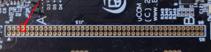
On the iMX8M boards PWM1 is available as GPIO_B on the uCOM Carrier Board. The best place to access the signal is on the expansion connector, J15-8.
iMX93 uCOM
The iMX93 have all 4 PWM channels on the Timer/PWM Module TPM4 mapped in the device tree. However, it is disabled in the device tree as there is a pin conflict with CAN2.
To enable the use of PWM, set the cmd_custom U-Boot environment variable with one of these options:
-
In U-Booot:
=> setenv cmd_custom fdt set /soc@0/bus@42000000/can@425b0000 status disabled\;fdt set /soc@0/bus@42000000/pwm@424f0000 status okay
=> saveenv -
Linux:
# fw_setenv cmd_custom fdt set /soc@0/bus@42000000/can@425b0000 status disabled\;fdt set /soc@0/bus@42000000/pwm@424f0000 status okay
The PWM signals can now be accessed here:
| Signal | pwmchipX | Channel | Location |
|---|---|---|---|
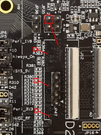
| TPM4.CH0 | pwmchip0 | pwm0 | LCDIF_D1, R371 |
| TPM4.CH1 | pwmchip0 | pwm1 | LCDIF_D14, R383 |
| TPM4.CH2 | pwmchip0 | pwm2 | LCDIF_D9, R378 |
| TPM4.CH3 | pwmchip0 | pwm3 | LCDIF_D21, JP35-2 |
The TPM driver requires duty_cycle to be smaller than period. The default values for both are 0, so trying to enable the pwm before setting period or having the wrong duty_cycle will cause an error like this: -sh: echo: write error: Invalid argument
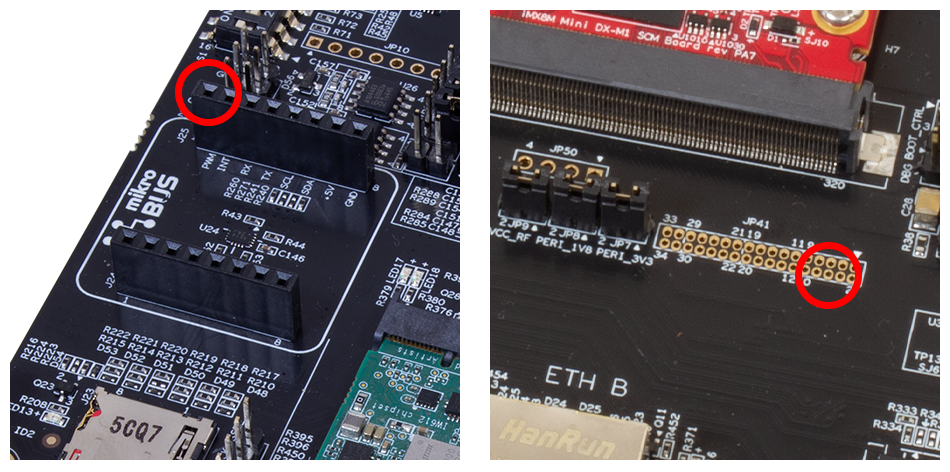
| Board | Channels | Example PWM |
|---|---|---|
| iMX8M Mini SOM | 4 | pwm1 |
iMX8M Mini SOM
The iMX8M Mini SOM support 4 PWM channels each, but only one is enabled - PWM1.
On the iMX8M boards PWM1 is available as GPIO_B on the SOM Carrier Board. The signal is available on the Mikrobus interface, connector J25 pin 1. It is also available on Expansion connector JP41 pin 6
U-Boot
Not currently available.
Linux
To see which PWM channels have been enabled in the device tree.
ls /sys/class/pwm/
pwmchip0 pwmchip1
In this case (iMX6 DualLite) two channels are enabled. On an iMX6 SoloX board with all channels enabled it would look like this.
ls /sys/class/pwm/
pwmchip0  pwmchip1  pwmchip2  pwmchip3
pwmchip4  pwmchip5  pwmchip6  pwmchip7
Each PWM channel has its own pwmchipX folder with a couple of interesting files.
ls /sys/class/pwm/pwmchip0/
device     export  npwm      power
subsystem  uevent  unexport
The export/unexport files work in the same way as for gpio. To use a pwm channel it must first be exported.
echo 0 > /sys/class/pwm/pwmchip1/export
It will then appear as a pwm0 node.
ls /sys/class/pwm/pwmchip1/pwm0
capture   duty_cycle   enable   period
polarity  power        uevent
To set the PWM frequency to 100 kHz (100kHz equals 10000 ns period time) and set the duty cycle to 70% (0.7 * period time equals 7000).
cd /sys/class/pwm/pwmchip1/pwm0
echo 10000 > period
echo 7000 > duty_cycle
echo 1 > enable
This signal can then be observed either with an oscilloscope or by measuring with a multimeter that will typically measure an average voltage. In this case the average should be ca 2.3V which is 70% of 3.3V.