UART
COM Carrier board Differences
- COM Carrier Board V1
- COM Carrier Board V2
- uCOM Carrier Board V3
- SOM Carrier Board
The COM Carrier Board V1 has three UARTs.
| Board | NXP name | Linux | Carrier board |
|---|---|---|---|
| iMX6 SoloX COM | UART1 UART2 UART5 | /dev/ttymxc0 (console) /dev/ttymxc1 /dev/ttymxc4 | Pin list J35 (UART-A) Pin list J15 (UART-B) Pin list J16 (UART-C) |
| iMX6 Quad COM | UART1* UART4* UART5 | /dev/ttymxc0 /dev/ttymxc3 (console) /dev/ttymxc4 | Pin list J16 (UART-C) Pin list J35 (UART-A) Pin list J15 (UART-B) |
| iMX6 DualLite COM | UART1* UART4* UART5 | /dev/ttymxc0 /dev/ttymxc3 (console) /dev/ttymxc4 | Pin list J16 (UART-C) Pin list J35 (UART-A) Pin list J15 (UART-B) |
| iMX6 UltraLite COM | UART1 UART2 UART3 | /dev/ttymxc0 (console) /dev/ttymxc1 /dev/ttymxc2 | Pin list J35 (UART-A) Pin list J15 (UART-B) Pin list J16 (UART-C) |
| iMX7 Dual (u)COM | UART1 UART2 UART3 | /dev/ttymxc0 (console) /dev/ttymxc1 /dev/ttymxc2 | Pin list J35 (UART-A) Pin list J15 (UART-B) Pin list J16 (UART-C) |
* - The console uses UART4 on iMX6 Quad and iMX6 DualLite starting with U-Boot version 2018.03 and Linux version 4.14.78. Older U-Boot and Linux versions use UART1.
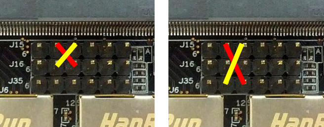
UART-A is used by the console, so it is tested by connecting a terminal program to the port and then boot into the U-Boot.
Two jumper cables are needed to run these tests. For iMX6 Quad and DualLite COM boards running an older version of U-Boot and Linux use UART-C as console, connect as in the right image below. For all other COM boards or connect as shown in the left image below.
COM Carrier Board V2 has an onboard Dual USB to serial IC making the external FTDI cable obsolete. The default position of the jumpers and the settings in both Linux and the U-Boot have been made so that the console always ends up on UART-A.
| Board | NXP name | Linux | Carrier board |
|---|---|---|---|
| iMX6 SoloX COM | UART1 UART2 UART5 | /dev/ttymxc0 (console) /dev/ttymxc1 /dev/ttymxc4 | UART-A UART-B UART-C |
| iMX6 Quad COM | UART1 UART4 UART5 | /dev/ttymxc0 /dev/ttymxc3 (console) /dev/ttymxc4 | UART-C UART-A UART-B |
| iMX6 DualLite COM | UART1 UART4 UART5 | /dev/ttymxc0 /dev/ttymxc3 (console) /dev/ttymxc4 | UART-C UART-A UART-B |
| iMX6 UltraLite COM | UART1 UART2 UART3 | /dev/ttymxc0 (console) /dev/ttymxc1 /dev/ttymxc2 | UART-A UART-B UART-C |
| iMX7 Dual (u)COM | UART1 UART2 UART3 | /dev/ttymxc0 (console) /dev/ttymxc1 /dev/ttymxc2 | UART-A UART-B UART-C |
| iMX7ULP uCOM | LPUART4 LPUART0 | /dev/ttyLP0 (console) /dev/ttyLP2 | UART-A UART-B |
| iMX8M Quad COM | UART1 UART2 UART3 | /dev/ttymxc0 (console) /dev/ttymxc1 /dev/ttymxc2 | UART-A UART-B UART-C |
| iMX8M Mini uCOM | UART1 UART2 | /dev/ttymxc0 /dev/ttymxc1 (console) | UART-B UART-A |
| iMX8M Nano uCOM | UART1 UART2 | /dev/ttymxc0 /dev/ttymxc1 (console) | UART-B UART-A |
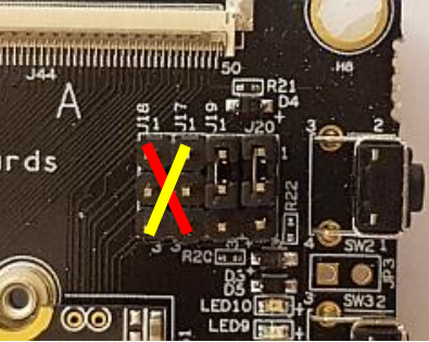
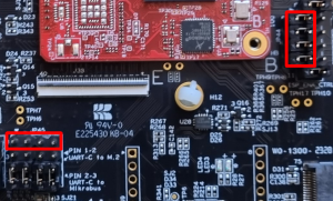
Two jumper cables are needed for this test. Connect as shown in the image below (J17-1 to J18-3, J17-3 to J18-1). Please note that for boards that only support two UARTs (such as iMX8M Mini) it is not possible to do this test.
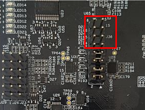
Before doing the UART test, four jumpers must be removed. It is the top four positions for J36 as shown in the figure below. When the jumpers are inserted the UART interfaces will be used by the Bluetooth interface on the M.2 connector.
This does not work on revision PE23 of the COM Carrier Board V2 since the jumpers are not available on that revision.
The uCOM Carrier Board V3 has an onboard Dual USB to serial IC making the external FTDI cable obsolete. The default position of the jumpers and the settings in both Linux and the U-Boot have been made so that the console always ends up on UART-A. As the name suggests, the uCOM Carrier Board only support the uCOM form factor and not the COM form factor.
| Board | NXP name | Linux | Carrier board |
|---|---|---|---|
| iMX8M Mini uCOM | UART1 UART2 UART4 | /dev/ttymxc0 (M.2) /dev/ttymxc1 (console) Used by Cortex-M | UART-C UART-A UART-B |
| iMX8M Nano uCOM | UART1 UART2 UART4 | /dev/ttymxc0 (M.2) /dev/ttymxc1 (console) Used by Cortex-M | UART-C UART-A UART-B |
| iMX93 uCOM | UART1 UART2 UART5 | /dev/ttyLP0 (console) Used by Cortex-M /dev/ttyLP4 (M.2) | UART-A UART-B Via JTAG interface* |
* - The UART is available on the JTAG pins, see more below
UART-B is by default reserved for the Cortex-M as its console. Instructions for using it from the Cortex-A can be found in Changing Console UART.
iMX8M Mini and iMX8M Nano uCOM
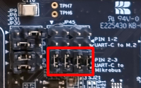
UART-C (i.e. UART1) is set up in the dts to be used by M.2 modules for Bluetooth. To use UART-C directly, four jumpers must be moved into correct positions. UART-C is normally directed to the M.2 connector for Bluetooth, but that must be disabled. Move JP21, JP22, JP23 and JP24 into the 2-3 position as shown in the figure below. UART-C will now be accessible on the Mikrobus/Click Module interface.
iMX93 uCOM
UART5 is set up in the dts to be used by M.2 modules for Bluetooth. The UART5 pins for the iMX93 are available on the JTAG pins (TCK, TMS, TDI and TDO) and by default those are connected to the M.2 Bluetooth pins. To use UART5 directly, make sure that there are no jumpers inserted in JP45 (left in the image) and that the jumpers in JP44 are in their default (left) position. The UART5 pins are now available on JP45.
The SOM Carrier Board has onboard USB to serial IC. The default position of the jumpers and the settings in both Linux and the U-Boot have been made so that the console always ends up on UART-A.
| Board | NXP name | Linux | Carrier board |
|---|---|---|---|
| iMX8M Mini SOM | UART1 UART2 UART4 | /dev/ttymxc0 (M.2) /dev/ttymxc1 (console) Used by Cortex-M | UART-B UART-A UART-C |
U-Boot
No special tests to run in the U-Boot. The console gets tested automatically and the other UARTs are not available.
Linux
Using a COM Carrier Board V1 or V2
The examples below are for the iMX6 UltraLite COM board on a V1 or V2 carrier board, so replace the devices according to the CPU you are testing.
To see which UARTs are available.
ls /dev/ttymxc*
/dev/ttymxc0 /dev/ttymxc1 /dev/ttymxc2
The console uses /dev/ttymxc0, so it does not need further testing.
To test /dev/ttymxc1/ and /dev/ttymxc2/ cross-connect the RX and TX lines on the COM Carrier Board as shown above.
After connecting, set them up with a baud rate of 115200, raw mode and no echoing.
stty -F /dev/ttymxc1 115200 raw -echo
stty -F /dev/ttymxc2 115200 raw -echo
To listen on /dev/ttymxc1 and send on /dev/ttymxc2.
cat /dev/ttymxc1 &
echo Hello World > /dev/ttymxc2
Hello World
The & in the first command above means that it will be executed in the background. Don't forget to stop the background process when you're done with it by bringing it to the foreground and then pressing Ctrl+C.
fg
cat /dev/ttymxc1
^C
Using a uCOM Carrier Board V3 or SOM Carrier Board
As can be seen in the table above, all the boards supported on the uCOM Carrier Board V3 or SOM Carrier board have an extra Cortex-M core and the second UART on those boards are reserved for the Cortex-M. The best way to verify that the UART for the Cortex-M side is working is to run one of the example programs, for example the TTY application.