CAN
| Board | CAN support in Linux |
|---|---|
| iMX6 SoloX COM | Yes |
| iMX6 Quad COM | Yes |
| iMX6 DualLite COM | Yes |
| iMX6 UltraLite COM | Yes |
| iMX7 Dual (u)COM | Yes |
| iMX7ULP uCOM | Not supported by CPU |
| iMX8M Quad COM | Not supported by CPU |
| iMX8M Mini uCOM/SOM | Not supported by CPU |
| iMX8M Nano uCOM | Not supported by CPU |
| iMX93 uCOM | Yes |
COM Carrier board Differences
- COM Carrier Board V1
- COM Carrier Board V2
- uCOM Carrier Board V3
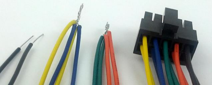
To run these tests the two CAN busses must be connected together. Use the cable that comes with the Carrier Board. Twist together the yellow and blue wires (CANH). Twist together the orange and green wires (CANL) as shown in the image below.

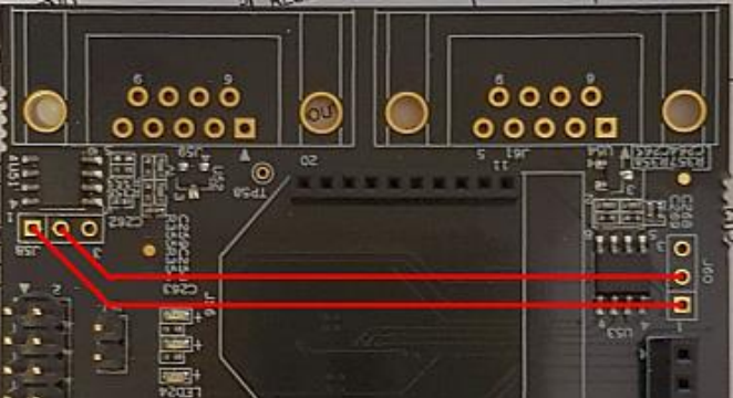
Two CAN interfaces are located on the Expansion Board (see User's Manual). The test below is based in connecting the two busses together which can be done with jumper cables as shown here.

Note that for iMX6 UltraLite CAN bus 2 has been disabled in the device tree file as it conflicts with one of the UARTs. Without modifying the device tree there is no way to run the CAN tests.
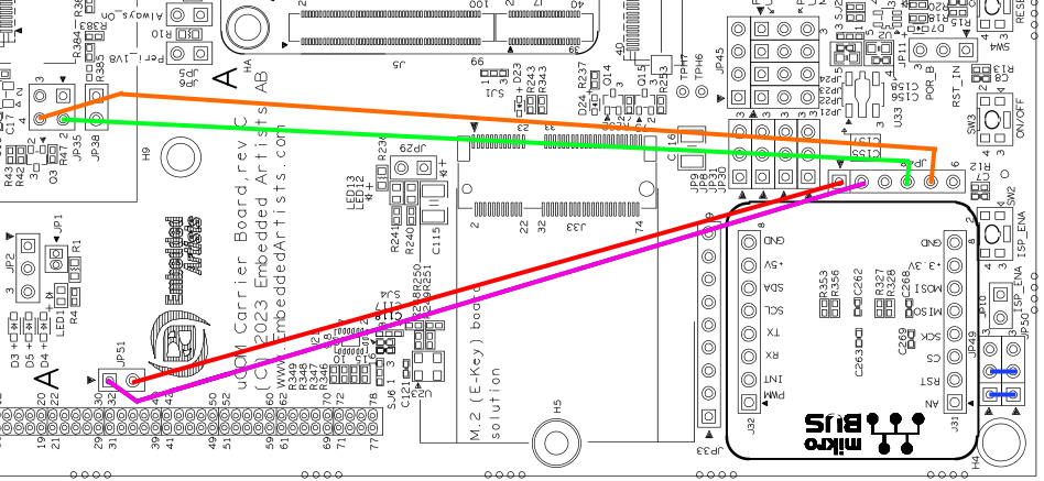
The uCOM Carrier Board V3 has two CAN transceivers available on connectors JP49 (CAN1) and JP50 (CAN2). To use the CAN bus on iMX93, a couple of jumper cables must be used:
| CAN Bus | Pin | Connect | iMX93 Pin Name |
|---|---|---|---|
| 1 | CAN1_TD | Connect JP51-2 to JP48-1 | MX93_PAD_PDM_CLK__CAN1_TX |
| 1 | CAN1_RD | Connect JP51-1 to JP48-2 | MX93_PAD_PDM_BIT_STREAM0__CAN1_RX |
| 2 | CAN2_TD | Connect JP35-2 to JP48-4 | MX93_PAD_GPIO_IO25__CAN2_TX |
| 2 | CAN2_RD | Connect JP35-4 to JP48-5 | MX93_PAD_GPIO_IO27__CAN2_RX |
In order to run the example code below, the two CAN busses must also be connected to each other like this:
| Pin | Connect |
|---|---|
| CAN1_H to CAN2_H | Connect JP49-1 to JP50-1 |
| CAN1_L to CAN2_L | Connect JP49-2 to JP50-2 |
This image shows all six connections:

U-Boot
CAN currently not supported.
Linux
Make sure that both can0 and can1 are detected.
ip link show
...
2: can0: <NOARP,ECHO> mtu 16 qdisc noop state DOWN mode DEFAULT
    group default qlen 10
    link/can
3: can1: <NOARP,ECHO> mtu 16 qdisc noop state DOWN mode DEFAULT
    group default qlen 10
    link/can
...
If the text <NOARP,ECHO> appears then the interface is down and must be brought up before it can be used.
ip link set can0 up type can bitrate 125000
ip link set can1 up type can bitrate 125000
As the interfaces are now up, the status will have changed.
ip link show
...
2: can0: <NOARP,UP,LOWER_UP,ECHO> mtu 16 qdisc pfifo_fast state
   UNKNOWN mode DEFAULT group default qlen 10
   link/can
3: can1: <NOARP,UP,LOWER_UP,ECHO> mtu 16 qdisc pfifo_fast state
   UNKNOWN mode DEFAULT group default qlen 10
   link/can
...
To test the CAN bus the two interfaces must be connected together as shown above.
The following example listens on can1 and sends on can0. Start by listening on the can1 interface in the background.
candump can1 &
Now send a message on can0 and see what arrives on can1.
cansend can0 5A1#11.2233.44556677.88
can1 5A1 [8] 11 22 33 44 55 66 77 88
The second line above is from the candump process and it shows that it has detected an 8 byte message with id 5A1 being received by the can1 interface.
After completing the tests, terminate the background process with the fg command and Ctrl+C.
fg
candump can1
^C